
PB 150 V8-318 5.2L VIN T 2-BBL (1983)
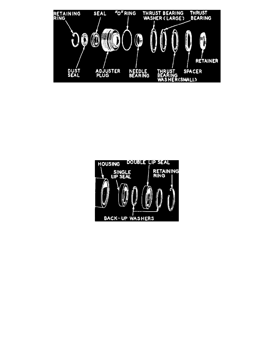
Fig. 17 Adjuster plug components
Lubricate all parts as they are assembled.
1. Screw lash adjuster through side cover until cover bottoms on pitman shaft gear. Install lash adjuster lock nut while holding lash adjuster with 7/32
inch Allen wrench.
2. Mount adjuster plug in vise with soft jaws.
3. If it has been removed, assemble needle bearing by pressing towards thrust bearing end of adjuster plug against identification end of bearing. End
of bearing to be flush with bottom surface of stub shaft seal bore.
4. Install stub shaft far enough to provide clearance for dust seal and retaining ring. Install new dust seal with rubber surface outward. Install new
retaining ring.
5. Assemble large thrust bearing race, thrust bearing, small race and spacer (with grooves up) on adjuster plug and secure with retainer.
Assemble Housing
Fig. 18 Pitman shaft seals & washers
1. With stamped end of needle bearing facing outward, drive bearing into bore from outside of housing until flush. Make sure bearings rotate freely.
2. Lubricate cavity between lips of pitman shaft (double lip) seal with power steering fluid.
3. Lubricate and install pitman shaft seals as shown. Make sure seal lips are properly positioned, retaining ring is seated.
4. If connectors were removed, install new ones by driving them into place.
Assemble Rotary Valve
1. Assemble one valve body Teflon ring back-up O-ring seal in each groove in valve body, being sure seals do not become twisted.
2. Assemble valve Teflon rings in ring grooves over O-ring seals by carefully slipping rings over valve body. The rings may appear loose or twisted
in the grooves but the heat of the oil during subsequent operation will cause them to straighten.
3. Install valve spool dampener O-ring seal in valve spool groove, being sure it is not twisted.
4. Insert stub shaft through valve spool, engaging spool locking pin.
5. Pull valve spool and stub shaft assembly into valve body, aligning stub shaft notch and valve body pin.
6. If used, slide spool spring over stub shaft and place into position.
7. Lubricate cap-to-worm O-ring and install in valve body. During assembly of the valve, if the stub shaft and cap is allowed to slip out of
engagement with the valve body pin, the spool will be permitted to enter the valve body too far. The dampener O-ring seal may expand into valve
body oil grooves, preventing removal of spool. If this happens, remove spool spring and disassemble rotary valve. Press on spool until O-ring seal
is cut and can be removed. Install new O-ring and reassemble.
Assemble Rack-Piston Worm & Valve