
PB 150 V8-318 5.2L VIN T 2-BBL (1983)
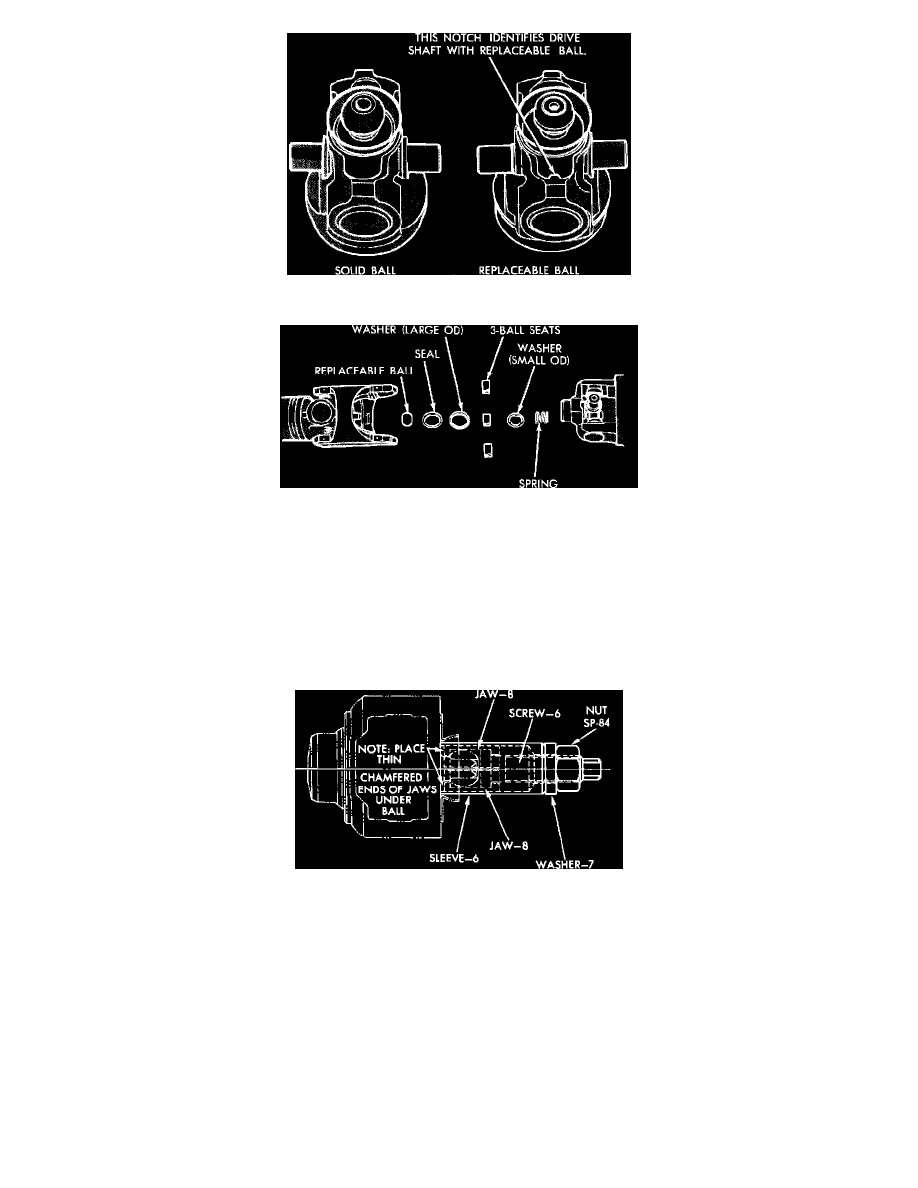
Fig. 14 Solid ball & replaceable balls. Notch identifies driveshaft w/replaceable ball
Fig. 15 Ball & seat exploded view
3. Press bearing cup out of coupling yoke ear. If bearing cup is not completely removed, insert spacer C-4365-4 or equivalent, and complete removal
of bearing cup.
4. Rotate driveshaft 180° and shear the opposite retaining ring, and press the bearing cup out of the coupling yoke as described previously, using
spacer C-4365-4 or equivalent.
5. Disengage cross trunnions, still attached to flange yoke, from coupling yoke. Pull flange yoke and cross from centering ball on ball support tube
yoke. The ball socket is part of the flange yoke. The ball on some joints is not replaceable. The joints with a replaceable ball can be recognized as
shown. Do not attempt to remove solid ball, as removal tool may be damaged.
6. Pry seal from ball cavity, then remove washers, spring and shoes.
Fig. 16 Removing centering ball
BALL SOCKET
1. To remove ball, separate universal joint between coupling yoke and flange yoke by pressing out trunnion bearing in coupling yoke. Pull flange
yoke and cross with ball socket from centering ball as a unit.
2. Clean and inspect ball seat insert bushing for wear. If worn, replace flange yoke and cross assembly.
3. Pry seal from ball cavity, then remove washers, spring and ball seats.
4. Clean and inspect centering ball surface, seal, ball seats, spring and washer. If parts are worn or broken, replace with a service kit.
5. Remove centering ball as shown, using components of tool C-4365 or equivalent. Install components as shown, and draw ball off ball stud.