
Prowler V6-3.5L VIN G (1999)
Power Door Lock Switch: Testing and Inspection
The Light-Emitting Diode (LED) illumination lamps for all of the power window and lock switch and bezel unit switch paddles receive battery current
through the power window circuit breaker in the junction block. If all of the LEDs are inoperative in either or both power window and lock switch and
bezel units, refer to Power Window Systems for diagnosis. If only one LED in a power window and lock switch and bezel unit is inoperative, replace the
faulty switch and bezel unit.
1. Check the fuse in the fuseblock. If OK, go to Step 2. If not OK, repair the shorted circuit or component as required and replace the faulty fuse.
2. Check for battery voltage at the fuse in the fuseblock. If OK, go to Step 3. If not OK, repair the open circuit to the Power Distribution Center
(PDC) as required.
3. Disconnect and isolate the battery negative cable. Remove the power window and lock switch and bezel unit from the door trim panel. Refer to
Power Windows for Door Lock/Window Switch Removal and Installation. Unplug the wire harness connector from the switch and bezel unit.
4. Connect the battery negative cable. Check for battery voltage at the fused B(+) circuit cavity of the body half of the power window and lock switch
and bezel unit wire harness connector. If OK, go to Step 5. If not OK, repair the open circuit from the fuse block to the switch as required.
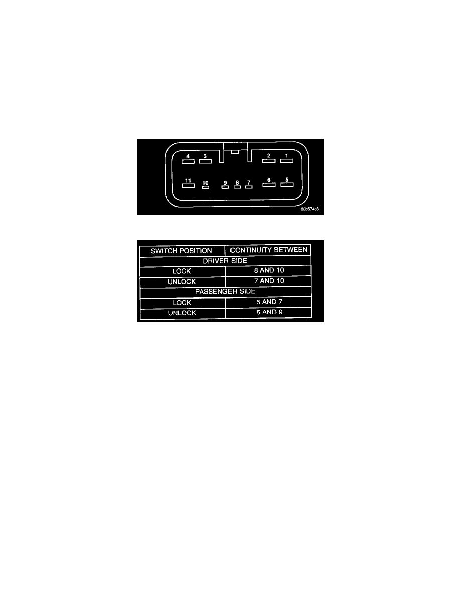
Power Door Lock/Window Switch Connector (Switch Side)
Power Lock Switch Continuity
5. Test the power lock switch continuity. See the Power Lock Switch Continuity charts to determine if the continuity is correct in the Lock and
Unlock switch positions. Refer to the Power Lock Switch Continuity test table. If OK, go to Step 6. If not OK, replace the faulty switch and bezel
unit.
NOTE: Cannot test for continuity thru LED's.
6. Refer to proper Body Diagnostic Procedures for Power Door Locks to diagnose the relays and output to the motors.
7. Disconnect wire connector from power door lock/window switch.
8. Using an ohmmeter, test switch continuity. Refer to and Power Lock Switch Continuity table.
9. If the results are NOT obtained as shown replace the door lock/power window switch.