
Prowler V6-3.5L VIN G (1999)
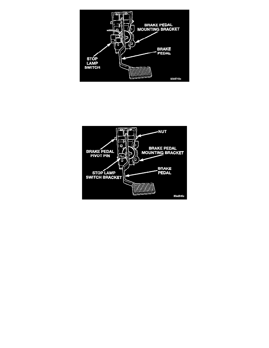
Stop Lamp Switch
7. Remove stop lamp switch from its bracket on the brake pedal mounting bracket. Stop lamp switch is removed using the following procedure.
Depress and hold the brake pedal while rotating stop lamp switch in a counter-clockwise direction approximately 30 degrees.
8. Remove the 2 nuts mounting brake pedal bracket to instrument panel bracket.
9. Remove brake pedal and mounting bracket as an assembly from the vehicle. The brake pedal and mounting bracket is removed out from under the
instrument panel on the left side of the steering column.
Brake Pedal Pivot Pin
10. Remove nut from brake pedal pivot pin. Remove brake pedal pivot pin from brake pedal and mounting bracket. Separate brake pedal from
mounting bracket.
Install
1. Lubricate brake pedal pivot pin and brake pedal bushings using Mopar Lubriplate or an equivalent.
2. Install brake pedal in mounting bracket. Install brake pedal pivot pin.
Caution: When tightening the brake pedal pivot pin attaching nut do not exceed the torque specification. If torque specification is exceeded the
brake pedal can bind causing the brakes to not fully release and the brake light to remain on. After tightening and torquing the pivot pin attaching
nut check the brake pedal to be sure it returns freely to the released position.
3. Install nut on brake pedal pivot pin. Tighten pivot pin attaching nut to a torque of 34 Nm (25 ft. lbs.).
4. Install brake pedal and mounting bracket as an assembly back in vehicle using the reverse sequence of its removal.
5. Loosely install the 2 nuts attaching the top of the brake pedal mounting bracket to the instrument panel mounting bracket. Do not tighten nuts at
this time, these nuts must be tightened after the nuts mounting the bracket to the vacuum booster studs are tightened.
6. Install nuts attaching pedal mounting bracket to vacuum booster mounting studs. Tighten mounting nuts to a torque of 23 Nm (200 inch lbs.).
7. Tighten the 2 nuts attaching brake pedal mounting bracket to instrument panel bracket to a torque of 20 Nm (180 inch lbs.).
8. Install wiring harness junction connector bracket on the right hand side mounting studs of vacuum booster. Tighten mounting nuts to a torque of
29 Nm (250 inch lbs.).
9. Using lubriplate, or an equivalent, coat brake pedal pin where it contacts vacuum booster input rod.
Note: When installing the vacuum booster input rod on the brake pedal pin the input rod must be positioned. The chamfer on the vacuum booster
input rod must facing the brake pedal arm when installed on the brake pedal pin. The retaining clip must be installed on the flat side of the vacuum
booster input rod.