
Prowler V6-3.5L VIN G (1999)
Brake Proportioning/Combination Valve: Service and Repair
Remove
1. Using a brake pedal depressor, move and lock the brake pedal to a position past its first 1 inch of travel. This will prevent brake fluid from
draining out of the master cylinder when the brake tubes are removed from the combination valve.
2. Raise vehicle on jackstands or centered on a hoist.
Caution: Before removing the brake tubes from the combination valve, the combination valve and the brake tubes must be thoroughly cleaned.
This is required to prevent contamination from entering the brake hydraulic system.
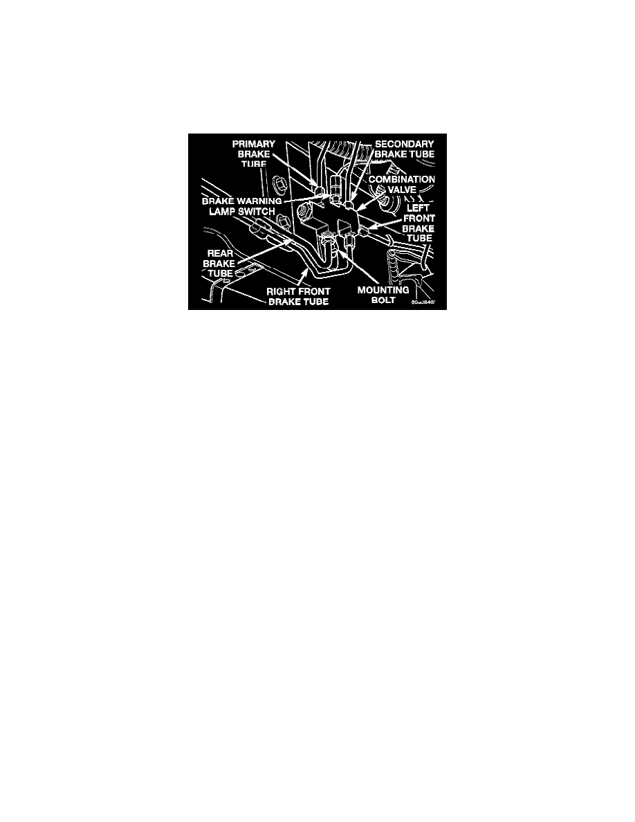
Combination Valve
3. Remove the wiring harness connector from the brake warning lamp switch located on the combination valve.
4. Remove the 5 chassis brake tubes from the combination valve.
5. Remove the bolt attaching the combination valve mounting bracket to the frame rail.
Install
1. Install the combination valve on the frame rail. Install the attaching bolt and tighten to a torque of 28 Nm (250 inch lbs.).
2. Install the 5 chassis brake tubes into the inlet and outlet ports on the combination valve. Tighten all 5 tube nuts to a torque of 16 Nm (145 inch
lbs.).
3. Install the wiring harness connector on the brake warning lamp switch.
4. Lower the vehicle.
5. Remove the brake pedal depressor.
6. Bleed the brake system thoroughly to ensure that all air has been expelled from the hydraulic system. Refer to Brake Bleeding for the proper
bleeding procedure.
7. Road test the vehicle to verify proper operation of the vehicles brake system.