
Prowler V6-3.5L VIN G (1999)
Control Assembly: Testing and Inspection
Temperature Reference Chart
NOTE: The control switch and timer circuit may be tested in the vehicle with or without scan tool (DRB).
TESTING WITH SCAN TOOL
If using the scan tool, refer to Powertrain Management/Computers and Control Systems/Body Control Module/Testing and
Inspection/Procedures/Diagnostic Charts.
TESTING WITHOUT SCAN TOOL
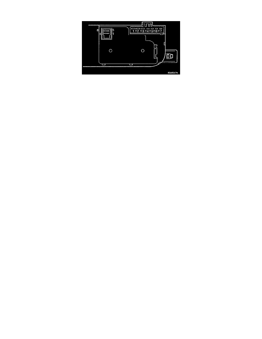
1. Remove the control switch from console and disconnect control switch.
2. Using a ohmmeter, check leads between Pins 5 and 8 of the 8-Way connector. Turn the control module to each position shown on chart below.
The resistance reading should be within the specifications shown.
CONTROL MODULE TEST CHART
Switch Position
Ohm Range
Defogger switch ON
499 to 520 ohms
Panel
828 to 856 ohms
Bi-Level
1.279k to 1.315k ohms
Floor
2.302k to 2.358k ohms
Mix
5.202k to 5.318k ohms
Defrost
99.5k to 101.5k ohms
If not OK, replace the control module.
If OK, check:
-
Blown fuse
-
Cut wire
-
Poor ground
-
Poor connection
-
Defective BCM
-
Bulkhead connector inoperative