
Prowler V6-3.5L VIN G (1999)
3. Operate the item.
4. The voltmeter will show the difference in voltage between the two points.
Troubleshooting Tools
TROUBLESHOOTING TOOLS
When diagnosing a problem in an electrical circuit, there are several common tools necessary. These tools are listed and explained below.
-
Jumper Wire - This is a test wire used to connect two points of a circuit. It can be used to bypass an open in a circuit.
WARNING: NEVER USE A JUMPER WIRE ACROSS A LOAD, SUCH AS A MOTOR, CONNECTED BETWEEN A BATTERY
FEED AND GROUND.
-
Voltmeter - This instrument is used to check for voltage on a circuit. Always connect the black lead to a known good ground and the red lead to
the positive side of the circuit.
CAUTION: Most of the electrical components used in today's vehicle are solid state. When checking voltages in these circuits, use a meter with a
10 megohm or greater impedance.
-
Ohmmeter - This instrument is used to check the resistance between two points of a circuit. Low or no resistance in a circuit can mean good
continuity or a shorted circuit.
CAUTION: Most of the electrical components used in today's vehicle are solid state. When checking resistance in these circuits, use a meter with
a 10 megohm or greater impedance. In addition, be sure the power is disconnected from the circuit. Circuits that are powered-up by the vehicle
electrical system can cause damage to the equipment and provide false readings.
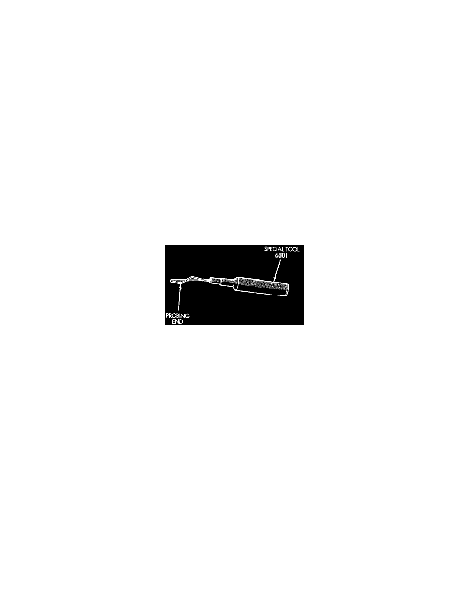
Probing Tool
-
Probing Tools - These tools are used for probing terminals in connectors. Select the proper size tool from Special Tool Package 6807 and insert it
into the terminal being tested. Use the other end of the tool to insert the meter probe.
Troubleshooting Wiring Problems
When troubleshooting wiring problems there are six steps which can aid in the procedure. The steps are listed and explained below. Always check for
non-factory items added to the vehicle before doing any diagnosis. If the vehicle is equipped with these items, disconnect them to verify these add-on
items are not the cause of the problem.
1. Verify the problem.
2. Verify any related symptoms. Do this by performing operational checks on components that are in the same circuit. Refer to the wiring diagrams.
3. Analyze the symptoms. Use the wiring diagrams to determine what the circuit is doing, where the problem most likely is occurring and where the
diagnosis will continue.
4. Isolate the problem area.
5. Repair the problem.
6. Verify proper operation. For this step check for proper operation of all items on the repaired circuit. Refer to the wiring diagrams.