
Prowler V6-3.5L VIN G (1999)
10. Spread the strands of the wire apart on each part of the exposed wires (Example 1).
11. Push the two ends of wire together until the strands of wire re close to the insulation (Example 2).
12. Twist the wires together (Example 3).
13. Solder the connection together using rosin core solder only. Do not use acid core solder.
14. Center the heat-shrink tubing over the joint and heat using a heat gun. Heat the joint until the tubing is tightly sealed and sealant comes out of both
ends of the tubing.
15. Insert the repaired wire into the connector.
16. Install the connector locking wedge, if required and re-connect the connector to its mating half/component.
17. Re-tape the wire harness starting 1-1/2 inches behind the connector and 2 inches past the repair.
18. Connect the battery and test all affected systems.
Terminal/Connector Repair-Augat Connectors
1. Disconnect battery
2. Disconnect the connector from its mating half/component.
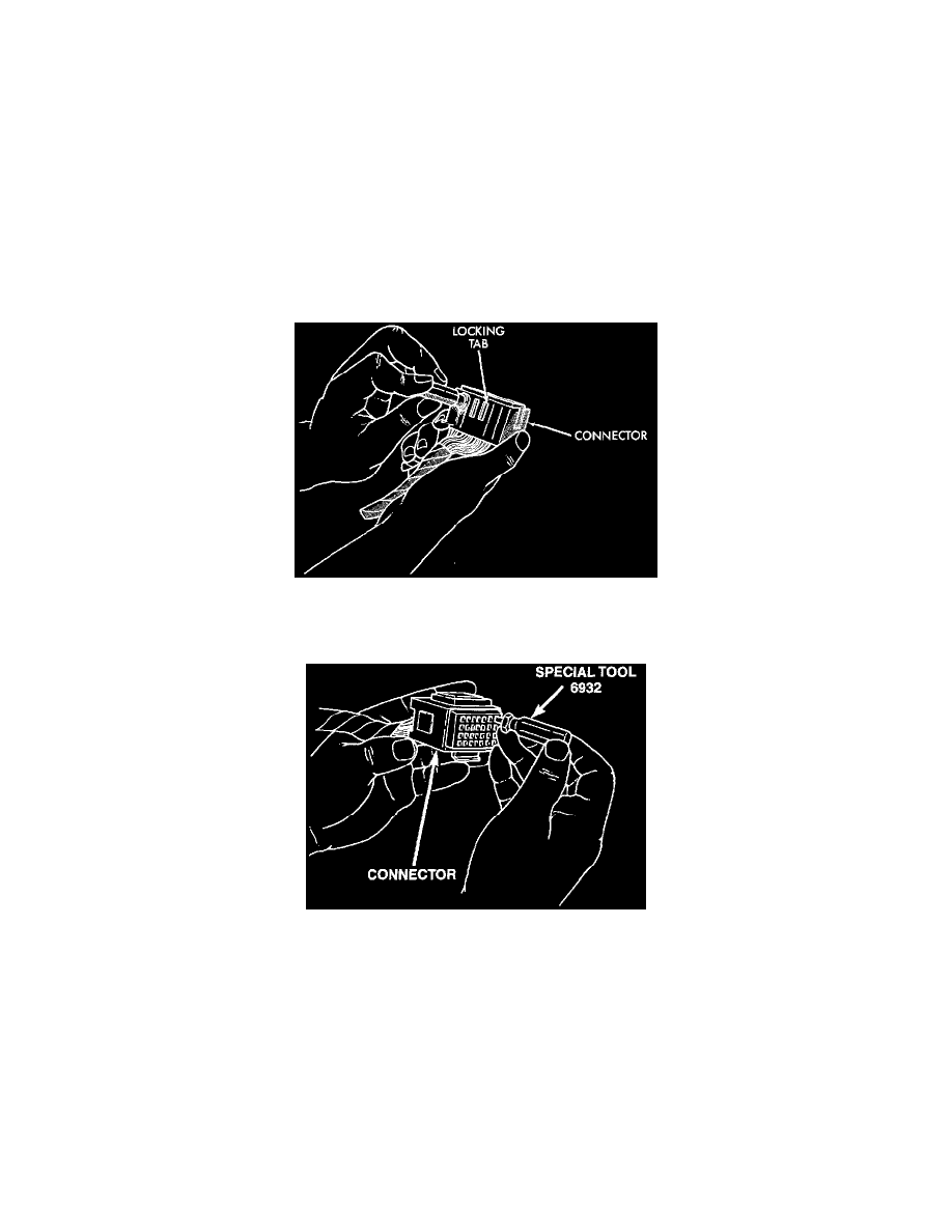
Augat Connector Repair
3. Push down on the yellow connector locking tab to release the terminals.
Using Special Tool 6932
4. Using Special Tool 6932, push the terminal to remove it from the connector.
5. Repair or replace the connector or terminal as necessary
6. When re-assembling the connector, the locking wedge must be placed in the locked position to prevent terminal push out.
Terminal/Connector Repair-Molex Connectors
1. Disconnect the battery.
2. Disconnect the connector from its mating half/component.