
Prowler V6-3.5L VIN G (1999)
Data Link Connector: Description and Operation
PURPOSE
Communication link to Powertrain Control Module (PCM).
Technician can access inputs and memory including:
-
Sensor input values
-
Diagnostic Trouble Codes (DTC's) stored in memory
-
Last deactivation cause (i.e. speed control last shut off by, speed control switch, brake switch, no crank sensor signal).
Technician can actuate most PCM output devices.
NOTE: Monitoring inputs, reading other memory and actuating output devices can only be accomplished through the use of a scan tool.
SCI RECEIVE-PCM INPUT
SCI Receive is the serial data communication receive circuit for the DRB scan tool. The Powertrain Control Module (PCM) receives data from the
DRB through the SCI Receive circuit.
DATA LINK CONNECTOR-PCM OUTPUT
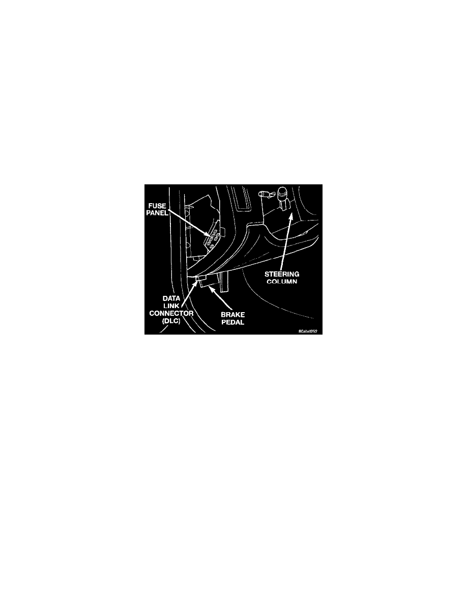
Data Link (Diagnostic) Connector
The data link connector (diagnostic connector) links the DRB scan tool with the Powertrain Control Module (PCM). The data link connector is
located inside the vehicle, below instrument panel next to the center column.