
Prowler V6-3.5L VIN G (1999)
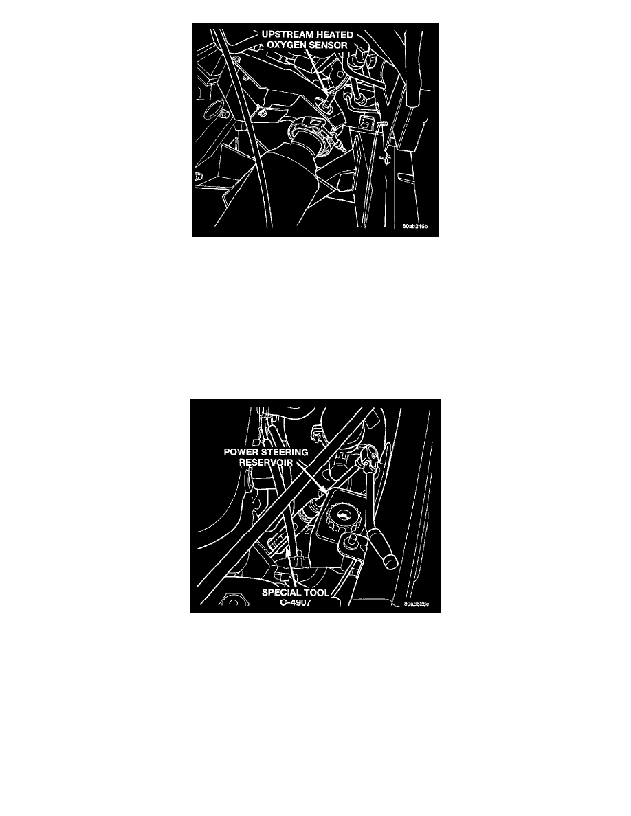
Upstream Heated Oxygen Sensor - Left Side
The engine uses two upstream heated oxygen sensors, one in each exhaust manifold.
WARNING: THE EXHAUST MANIFOLD, EXHAUST PIPES AND CATALYTIC CONVERTER BECOME VERY HOT DURING
ENGINE OPERATION. ALLOW ENGINE TO COOL BEFORE REMOVING OXYGEN SENSOR.
REMOVAL
CAUTION: When disconnecting the sensor electrical connector, do not pull directly on wire going into sensor.
1. Disconnect the heated oxygen sensor electrical connector.
Heated Oxygen Sensor Removal/Installation - Left Side
2. Use a socket such as Snap-On YA8875 or Special tool C4907A to remove oxygen sensor.
INSTALLATION
1. After removing the sensor, the exhaust manifold threads must be cleaned with an 18 mm X 1.5 + 6E tap. If reusing the original sensor, coat the
sensor threads with an anti-seize compound such as Loctite 771-64 or equivalent. New sensors have compound on the threads and do not require
an additional coating. Tighten the sensor to 28 Nm (20 ft. lbs.) torque.
2. Connect the heated oxygen sensor electrical connector.