
Prowler V6-3.5L VIN G (1999)
Leak Detection Pump: Description and Operation
Leak Detection Pump (LDP) Operation And Diagnosis
This bulletin describes the theory of operation for the leak detection system. In addition, information is provided for each of the Diagnostic Trouble
Codes (DTC's) as follows:
P0442-EVAP LEAK MONITOR 0.040" LEAK DETECTED
P0455-EVAP LEAK MONITOR LARGE LEAK DETECTED
P0456-EVAP LEAK MONITOR 0.020" LEAK DETECTED
P1486-EVAP LEAK MONITOR PINCHED HOSE FOUND
P1494-LEAK DETECTION PUMP SW OR MECHANICAL FAULT
P1495-LEAK DETECTION PUMP SOLENOID CIRCUIT
INTRODUCTION
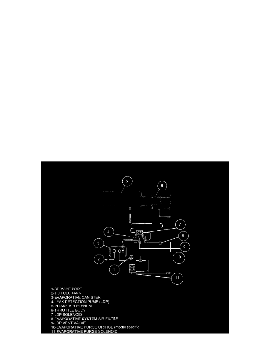
The evaporative emission system is designed to prevent the escape of fuel vapors from the fuel system. Leaks in the system, even small ones, can allow
fuel vapors to escape into the atmosphere. Government regulations require on-board testing to make sure that the evaporative (EVAP) system is
functioning properly. The leak detection system tests for EVAP system leaks and blockage. It also performs self-diagnostics.
During self-diagnostics, the Powertrain Control Module (PCM) first checks the Leak Detection Pump (LDP) for electrical and mechanical faults. If the
first checks pass, the PCM then uses the LDP to seal the vent valve and pump air into the system to pressurize
it. If a leak is present, the PCM will continue pumping the LDP to replace the air that leaks out. The PCM determines the size of the leak based on how
fast/long it must pump the LDP as it tries to maintain pressure in the system.