
Prowler V6-3.5L VIN G (1999)
Remote Switch: Testing and Inspection
WARNING: ON VEHICLES EQUIPPED WITH AIRBAGS, REFER TO AIR BAGS AND SEAT BELTS/AIR BAGS SYSTEMS BEFORE
ATTEMPTING ANY STEERING WHEEL, STEERING COLUMN, OR INSTRUMENT PANEL COMPONENT DIAGNOSIS OR SERVICE.
FAILURE TO TAKE THE PROPER PRECAUTIONS COULD RESULT IN ACCIDENTAL AIR-BAG DEPLOYMENT AND POSSIBLE
PERSONAL INJURY.
1. Disconnect and isolate the battery negative cable. Wait two minutes for the airbag system capacitor to discharge before further service.
2. Remove the remote radio switch(es) from the steering wheel. Refer to Remote Radio Switch Removal and Installation.
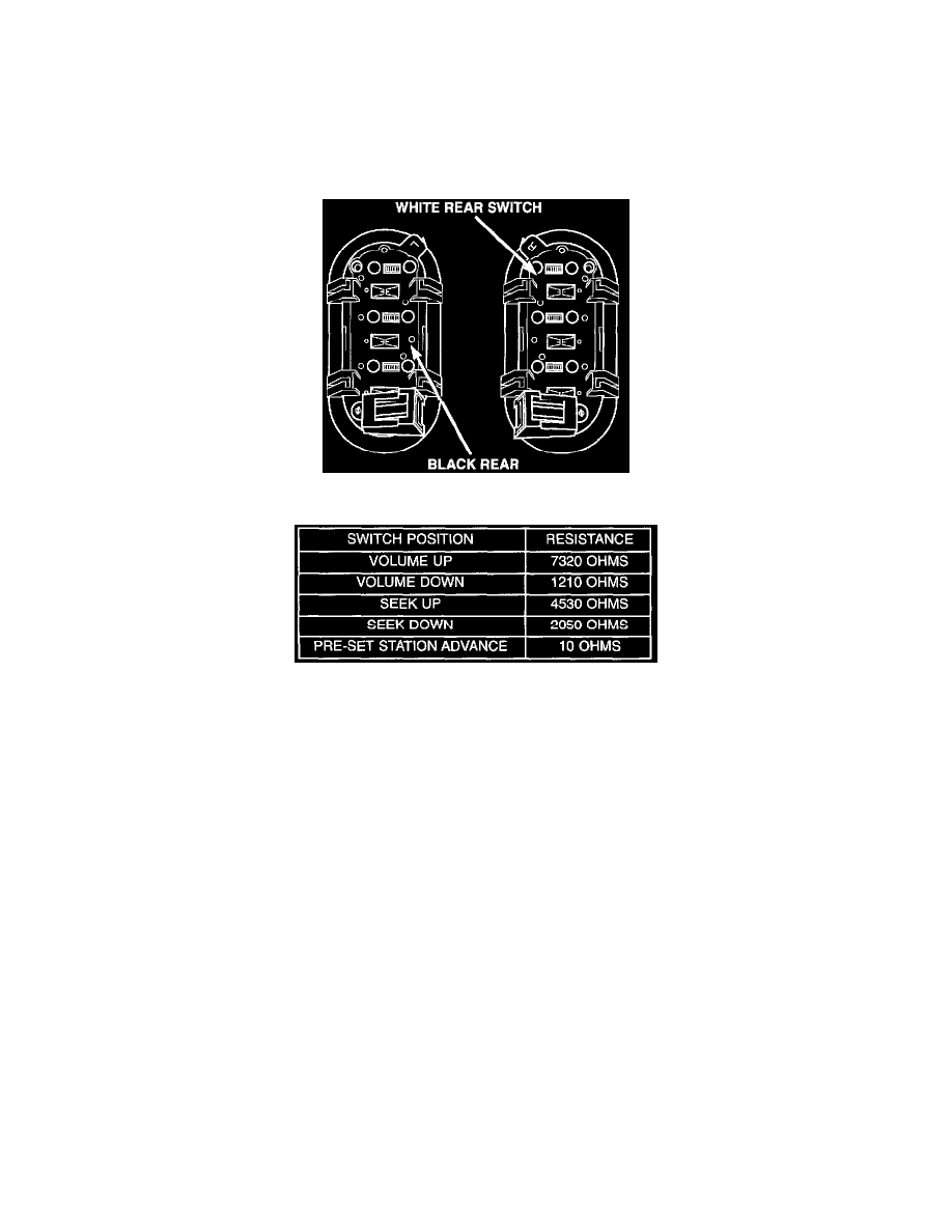
Remote Radio Switches
Remote Radio Switch Test
3. Use an ohmmeter to check the switch resistance as shown in the Remote Radio Switch Test table.
NOTE: The right remote radio switch back is white in color. The left switch back is black in color. The right/left remote radio switch orientation
is with the steering wheel installed, and driver in drivers seat.
4. If the switch resistance checks OK, go to Step 5. If not OK, replace the faulty switch.
5. Check for continuity between the ground circuit cavity of the switch wire harness connector and a good ground. There should be continuity If OK,
go to Step 6. If not OK, repair the open circuit as required.
6. Unplug the 24-way white wire harness connector from the Body Control Module (BCM). Check for continuity between the radio control circuit
cavity of the remote radio switch wire harness connector and a good ground. There should be no continuity. If OK, go to Step 7. If not OK, repair
the short circuit as required.
7. Check for continuity between the radio control circuit cavities of the remote radio switch wire harness connector and the BCM wire harness
connector. There should be continuity. If OK, refer to the proper Diagnostic Procedures to test the BCM and the CCD data bus. If not OK, repair
the open circuit as required.
For further remote radio switch diagnosis and testing, refer to the proper Body Diagnostic Procedures.