
Prowler V6-3.5L VIN G (1999)
Fuel Gauge Sender: Testing and Inspection
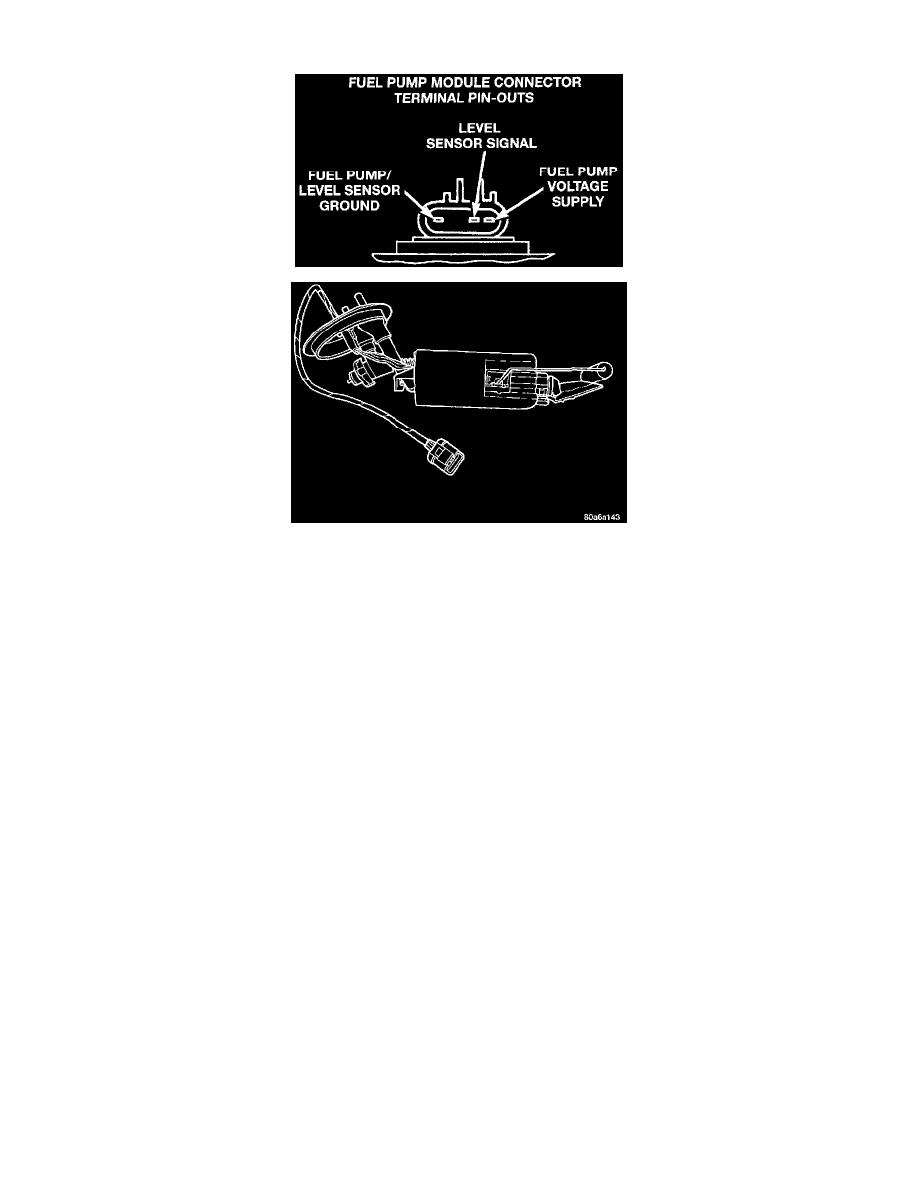
Fig. 1 Fuel Pump Module - Typical
The level sensor is attached to the side of the fuel pump module. The level sensor consists of a float, an arm, and a variable resistor. As the fuel
level increases, the float and arm move up. This decreases the sending unit resistance, causing the fuel gauge on the instrument panel to read full.
This procedure tests the resistance of the level sensor itself. It does not test the level sensor circuit.
The level sensor is a variable resistor. Its resistance changes with the amount of fuel in the tank. The float arm attached to the sensor moves as the
fuel level changes. To test the level sensor, connect an ohmmeter across the sensor signal and sensor ground terminals of the fuel pump module
connector. Move the float lever to the positions shown. Record the resistance at each point.
-
Sensor Full Stop ................................................................................................................................................................................ 50 - 90 ohms
-
Sensor Empty Stop .................................................................................................................................................................... 1020 - 1080 ohms
Replace the level sensor if the resistance is not within specifications.