
Prowler V6-3.5L VIN G (1999)
Part 2 Of 2
Chrysler wiring diagrams are designed to provide information regarding the vehicles wiring content. In order to effectively use Chrysler wiring diagrams
to diagnose and repair a Chrysler vehicle, it is important to understand all of their features and characteristics.
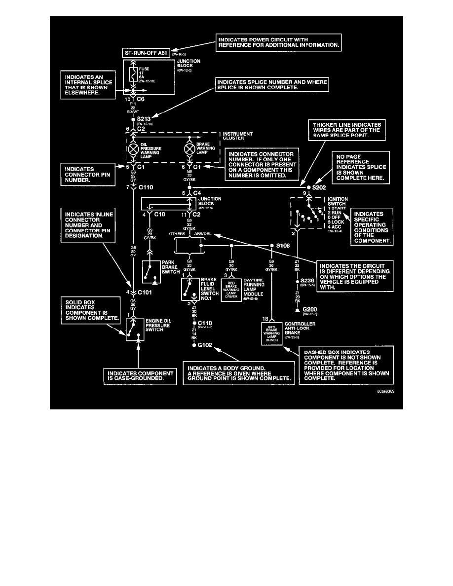
Diagrams are arranged such that the power (B+) side of the circuit is placed near the top of the sheet, and the ground (B-) side of the circuit is placed
near the bottom of the sheet.
All switches, components, and modules are shown in the at rest position with the doors closed and the key removed from the ignition.
Components are shown two ways. A solid line around a component indicates that the component is complete. A dashed line around a component
indicates that the component being shown is not complete. Incomplete components have a reference number to indicate the sheet where the component is
shown complete.
It is important to realize that no attempt is made on the diagrams to represent components and wiring as they appear on the vehicle. For example, a short
piece of wire is treated the same as a long one. In addition, switches and other components are shown as simply as possible, with regard to function only.