
Prowler V6-3.5L VIN G (1999)
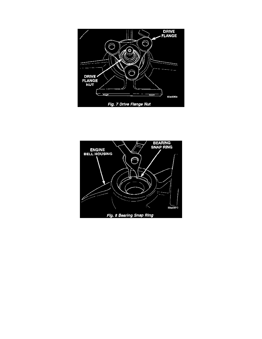
Fig. 6
1. Remove flex plate adapter bolts (Fig. 5) (Fig. 6).
Fig. 7
2. Remove engine bell housing drive flange nut. Use a deep 1 1/4 inch socket (Fig. 7).
3. Slide flange off of the output shaft.
4. Remove output shaft from housing.
Fig. 8
5. Remove bearing snap ring from housing (Fig. 8).
6. Position Special Tool #6310-1 cup underneath bell housing nose.
7. Drive out bearing using Special Tool # 6597 driver, and Special Tool # C-4171 handle.
ASSEMBLY
1. Install bell housing in shop press.
2. Position bearing into bell housing nose.
3. Drive bearing into bell housing using Special Tool # C-4628 driver (inverted) and Special Tool # C-4171 handle.
4. Install snap ring into engine bell housing.
5. Install output shaft.
6. Install drive flange. Tighten flange nut using Special Tool # 6958 holder. Torque flange nut to 100 Nm (75 ft. lbs.).
Cleaning and Inspection
BEARING INSPECTION
After engine bell housing bearing removal, inspect the bearing for wear. The bearing is designed for the life of the vehicle and requires no periodic
maintenance. The following procedure can be used to inspect the condition of the bearing.
With the bearing removed, rotate the inner race of the bearing in the palm of your hand while pushing down slightly. Any roughness or resistance to