
Prowler V6-3.5L VIN G (1999)
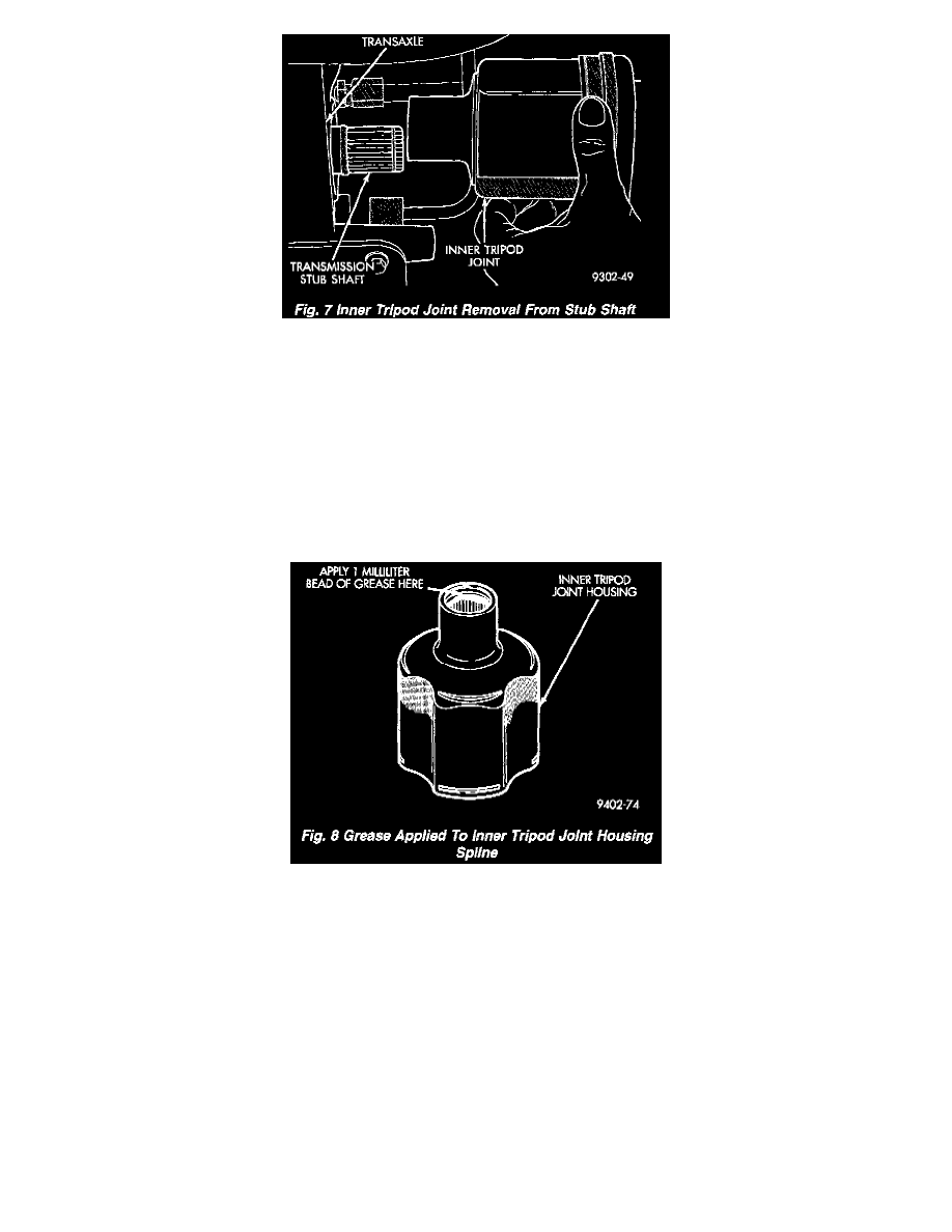
Fig. 7
13. Remove halfshaft inner tripod joint from transaxle stub shaft. When removing halfshaft, do not pull on interconnecting shaft to remove inner tripod
joint from stub shaft. Removal in this manner will separate the spider assembly from the tripod joint housing. Grasp inner tripod joint and
interconnecting shaft and pull on both pieces at the same time.
INSTALLATION
CAUTION: The inboard tripod joint retaining circlip and O-ring seal on the transaxle stub shaft are not re-usable. Whenever the inboard tripod joint
is removed from the stub shaft, the retaining circlip and O-ring seal MUST BE REPLACED. The retaining circlip and O-ring seal is included in all
service kits requiring removal of the inboard tripod joint from the stub shaft.
1. Replace O-ring seal and tripod joint retaining circlip on the transaxle stub shaft.
Fig. 8
2. Evenly apply a bead of grease, such as MOPAR Multi-Purpose Lubricant or an equivalent, around spline (of inner tripod joint where the O-ring
seats against tripod joint. This will spread grease onto stub shaft during tripod joint installation preventing corrosion and help to seal the O-ring.
3. Align and position halfshaft; at transaxle stub shaft. Grasp inner tripod joint in one hand and interconnecting shaft in the other. Align inner tripod
joint spline with stub shaft spline on transaxle. Use a rocking motion with the inner tripod joint, to get it past the circlip on the transaxle stub shaft.
4. Continue pushing tripod joint onto transaxle stub shaft until it stops moving. The O-ring seal on the stub should not be visible when inner tripod
joint is fully installed on stub shaft. To check that inner tripod joint retaining circlip is locked into tripod joint, grasp inner tripod joint and pull on
it by hand. If circlip is locked into tripod joint, tripod joint will not move on stub shaft.
CAUTION: When installing outer C/V joint into the hub and bearing assembly, do not allow the flinger disk on hub and bearing assembly to
become damaged. Damage to the flinger disk can cause dirt and water intrusion into bearing and premature bearing failure.
5. Pull out on tire and knuckle and engage outer joint into knuckle and hub.
6. Install outer C/V joint into the hub and bearing assembly.
7. Position ball stud to rear knuckle.
8. Carefully insert ball stud into rear knuckle.