
Prowler V6-3.5L VIN G (1999)
Power Window Switch: Testing and Inspection
The Light-Emitting Diode (LED) illumination lamps for all of the power door lock/window switch paddles receive ignition current through the power
window circuit breaker in the relay bank. If all of the LEDs are inoperative in either or both power window and lock switch and bezel units and the
power windows are inoperative, perform the diagnosis for Power Window System. If the power windows operate, but any or all of the LEDs are
inoperative, the power window and lock switch and bezel unit with the inoperative LED(s) is faulty and must be replaced. For circuit descriptions and
diagrams, refer Power Windows.
1. Check the circuit breaker in the junction block. If OK, go to Step 2. If not OK, replace the faulty circuit breaker.
2. Turn the ignition switch to the On position. Check for battery voltage at the circuit breaker in the junction block. If OK, turn the ignition switch to
the Off position and go to Step 3. If not OK, repair the circuit to the ignition switch as required.
3. Disconnect and isolate the battery negative cable. Remove the power door lock/window switch and bezel from the door trim panel. Refer to
Removal and Installation. Unplug the wire harness connector from the switch and bezel unit.
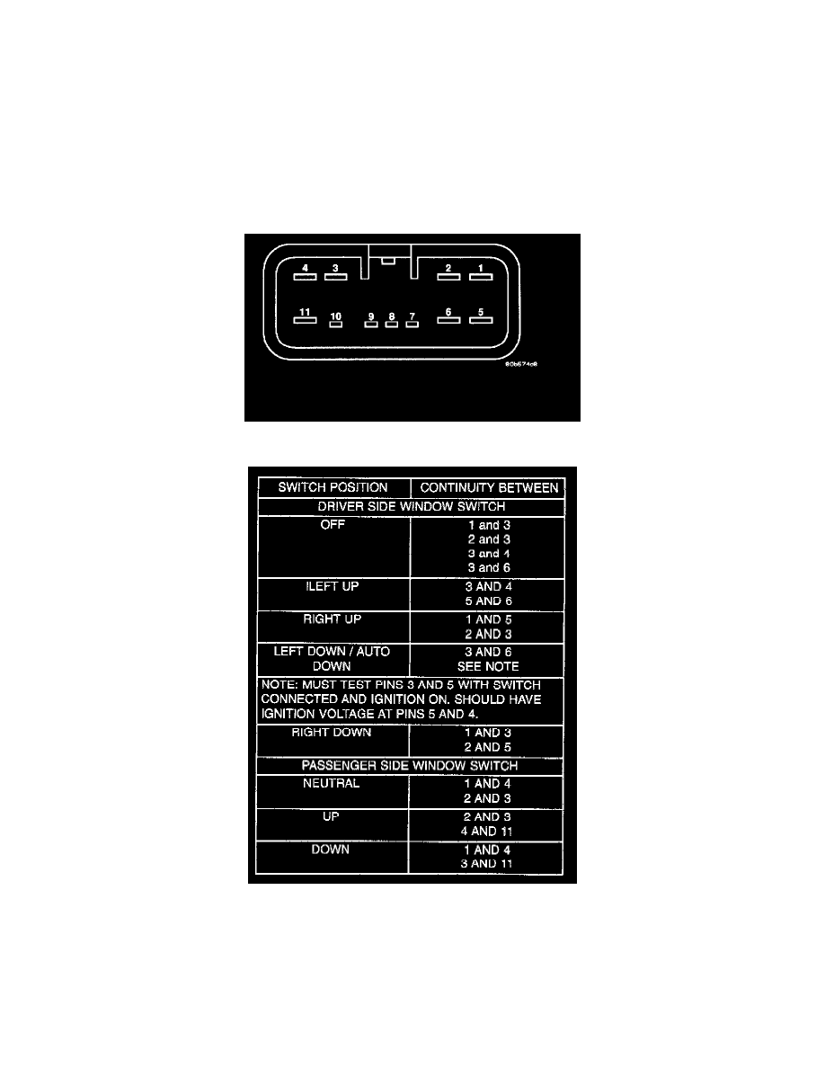
Power Door Lock/Window Switch Connector (Switch Side)
Power Window Switch Continuity
4. Test the power window switch continuity. See the Power Window Switch Continuity charts to determine if the continuity is correct in the Neutral,
Up and Down switch positions and Power Window Switch Continuity test table. If OK, see Power Window Motor in the Diagnosis and Testing. If
not OK, replace the faulty switch and bezel.
NOTE: Cannot read continuity thru LED's.