
Reliant-K L4-156 2.6L VIN G 2-bbl (1983)
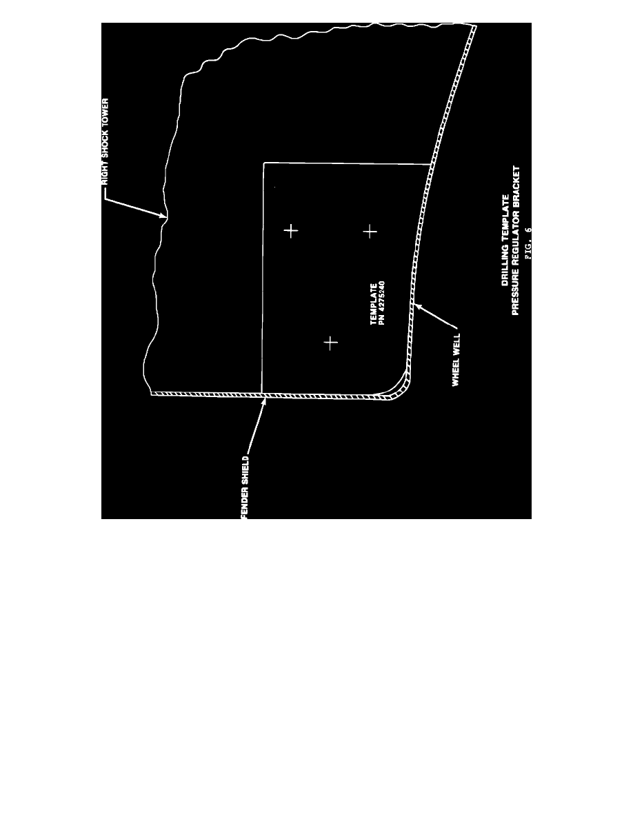
DRILLING TEMPLATE PRESSURE REGULATOR BRACKET FIG. 6
7.
To mount the pressure regulator, tape the pressure regulator bracket template, PN 4275240, to the right side shock tower as shown in Figure 6.
Carefully locate the template against the right fender shield and wheel well (keep the top side of the template level). Center punch three screw hole
locations and drill three .165" diameter (#21 drill) holes. Attach the pressure regulator bracket with three self-tapping screws, PN 6031991, tighten
securely.
NOTE:
SOME VEHICLES HAVE HEADLAMP-TO-DASH MAIN WIRING HARNESS ROUTING ATTACHED WITH A CLIP AT
THE RIGHT SHOCK TOWER. IF SO, THE HARNESS MAY NEED TO BE REROUTED TO ALLOW ROOM FOR
PRESSURE REGULATOR. REMOVE WIRING FROM EXISTING CLIP AT RIGHT SHOCK TOWER AND DISCARD CLIP.
DISCONNECT BOWL VENT HOSE CLIP LOCATED ON WHEEL WELL BELOW AND ROUTE HARNESS THROUGH
BOWL VENT HOSE CLIP. REATTACH BOWL VENT HOSE CLIP.