
Reliant-K L4-156 2.6L VIN G 2-bbl (1983)
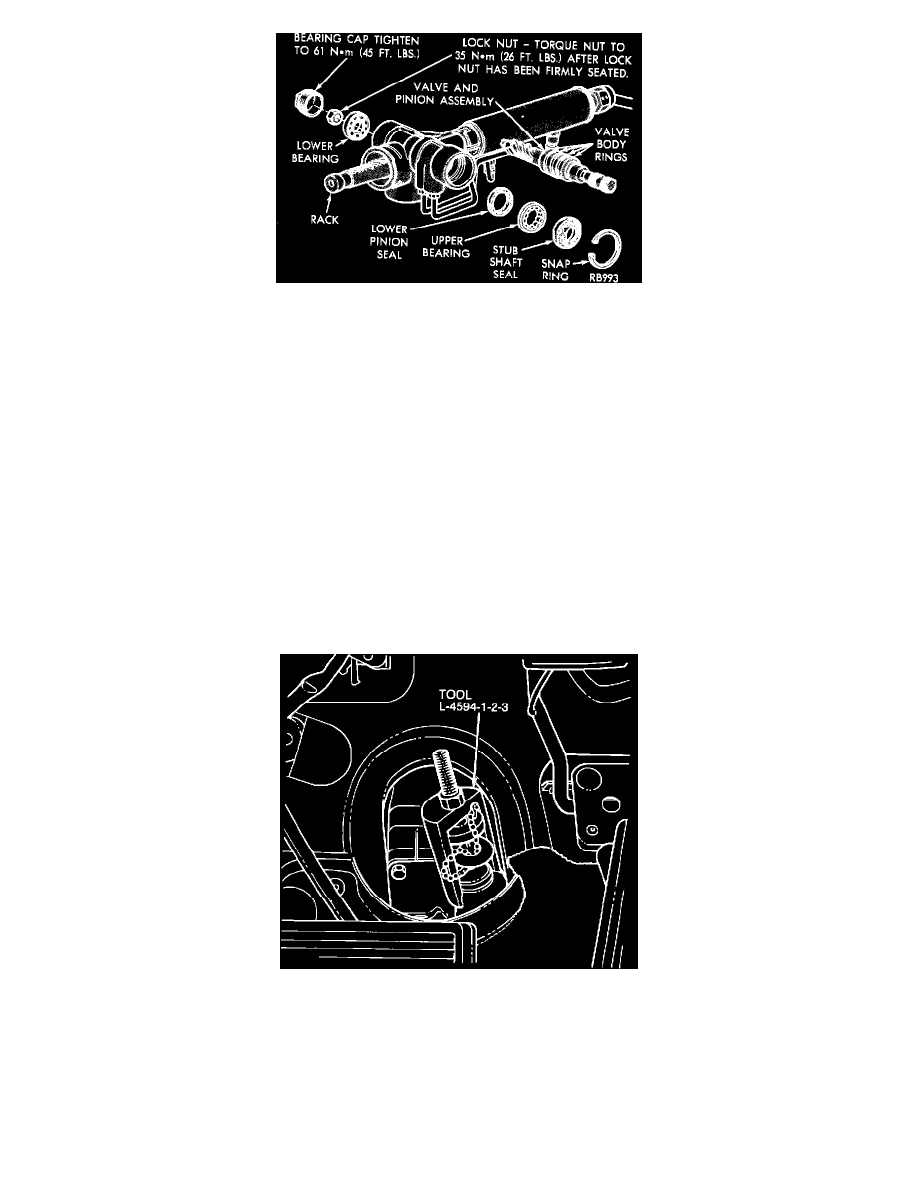
FIGURE 2 - STUB SHAFT SEALS (TRW)
C.
Remove pinion dust cover and lock nut (Saginaw) (Figure 1). Remove bearing cap and lock nut (TRW) (Figure 2).
NOTE:
IT MAY BE NECESSARY ON THE TRW ASSEMBLY TO LOOSEN THE RACK ASSEMBLY MOUNTING BOLTS AS
REQUIRED TO ROTATE RACK ASSEMBLY IN ORDER TO GAIN ACCESS TO THE BEARING CAP AND LOCK NUT.
When removing the lock nut have another person hold the steering wheel or lock steering wheel with ignition key to prevent damage to the pinion in
teeth.
D.
Remove the steering column and toe plate using the procedures in the appropriate service manual.
E.
Remove the steering shaft boot covering the pinion shaft and lower coupling on models so equipped and then raise vehicle and remove the lower
coupling-topinion shaft roll pin. Use a backup to protect universal joint while driving roll pin. Lower vehicle.
F.
Remove pressure and return lines at pinion housing and allow to drain into proper container.
NOTE:
THIS MUST BE DONE TO PREVENT P/S FLUID FROM PUMP AND RESERVOIR TO DRAIN INTO THE
MECHANICAL DRIVE AREA OF THE GEAR SET.
G.
Remove pinion stub shaft retaining ring.
FIGURE 3 - REMOVE VALVE & PINION ASSEMBLY (TRW & SAGINAW)
H.
Using Tool L-4594-1-2-3, pull valve and pinion (stub shaft) assembly (Figure 3) until the bearing assembly is flush with the pinion housing. Then
remove tools. Complete removal of valve and pinion assembly is not necessary.
NOTE:
TOOL ADAPTER L4594-7 IS REQUIRED FOR STUB SHAFT REMOVAL ON 1983 SAGINAW ASSEMBLY.