
Reliant L4-156 2.6L SOHC (1984)
TYPICAL CONTROL MODULE MOUNTING FIGURE 2-B
13.
Connect the control module, PN 5226640, to the natural colored 8-way connector on overlay harness, PN 4331801. Secure the module to the
instrument panel main wiring harness with a tie wrap, PN 6015756, close to the bulkhead connector (Figure 2-B).
14.
Reinstall engine side of bulkhead connector and torque to 40 inch pounds.
C.
Body Harness, PN 4331122, 4331855
1.
Remove the left side sill scuff plate and rear seat upper and lower cushions. Remove the spare tire.
2.
The existing wiring going through floor grommet to tank will not be used. Remove existing harness at floor grommet and locator clip on V
support. Route old harness down to area under rear seat cushion. Spot tape harness to V support and to floor panel so wiring does not rattle.
Old harness will be covered by rear seat cushion when reassembled.
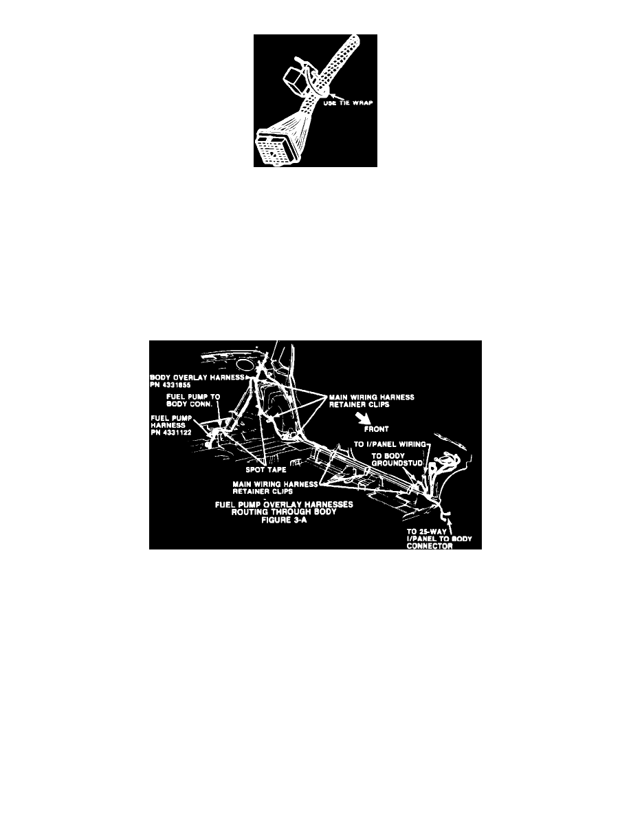
FIGURE 3-A - FUEL PUMP OVERLAY HARNESSES ROUTING THROUGH BODY
3.
Install sending unit jumper harness, PN 4331122, by feeding the black 5-way connector through the vacated grommet hole. Make sure
grommet on new harness is fully seated in body hole (Figure 3-A).
4.
Route the overlay harness, PN 4331855, along the left side rear wheel housing and along main body harness, working toward instrument
panel using the retainer clips indicated in Figure 3-A. Tape overlay harness to main harness as shown in Figure 3-A.
CAUTION:
MAKE SURE THAT THE OVERLAY HARNESS WILL NOT BE PINCHED BY THE SCUFF PLATE
FASTENING SCREWS DURING REINSTALLATION.