
Reliant L4-156 2.6L SOHC (1984)
5.
Attach the 7" long hose on the reservoir inlet to the fuel pump outlet nipple and clamp with hose clamp, PN 6500650 (Figure 1). Torque to 10 inch
pounds.
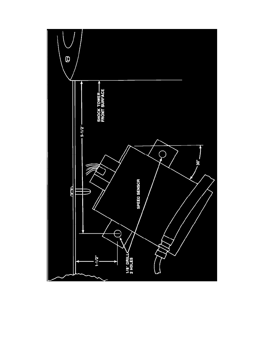
FIGURE 2 - SPEED SENSOR RELOCATION
6.
Vehicles equipped with a speed sensor on the right shock tower or right fender shield may have to have it relocated to allow room for pressure
regulator.
To relocate sensor, mark and drill 1/8" hole for upper sensor mount on right fender shield as shown in Figure 2. Re-attach sensor with upper screw.
Adjust the speed sensor to a 30~ angle as shown, center punch, and drill 1/8" hole for the second attaching screw. Install the second screw and
tighten both screws securely.