
Sundance L4-153 2.5L SOHC Turbo (1990)
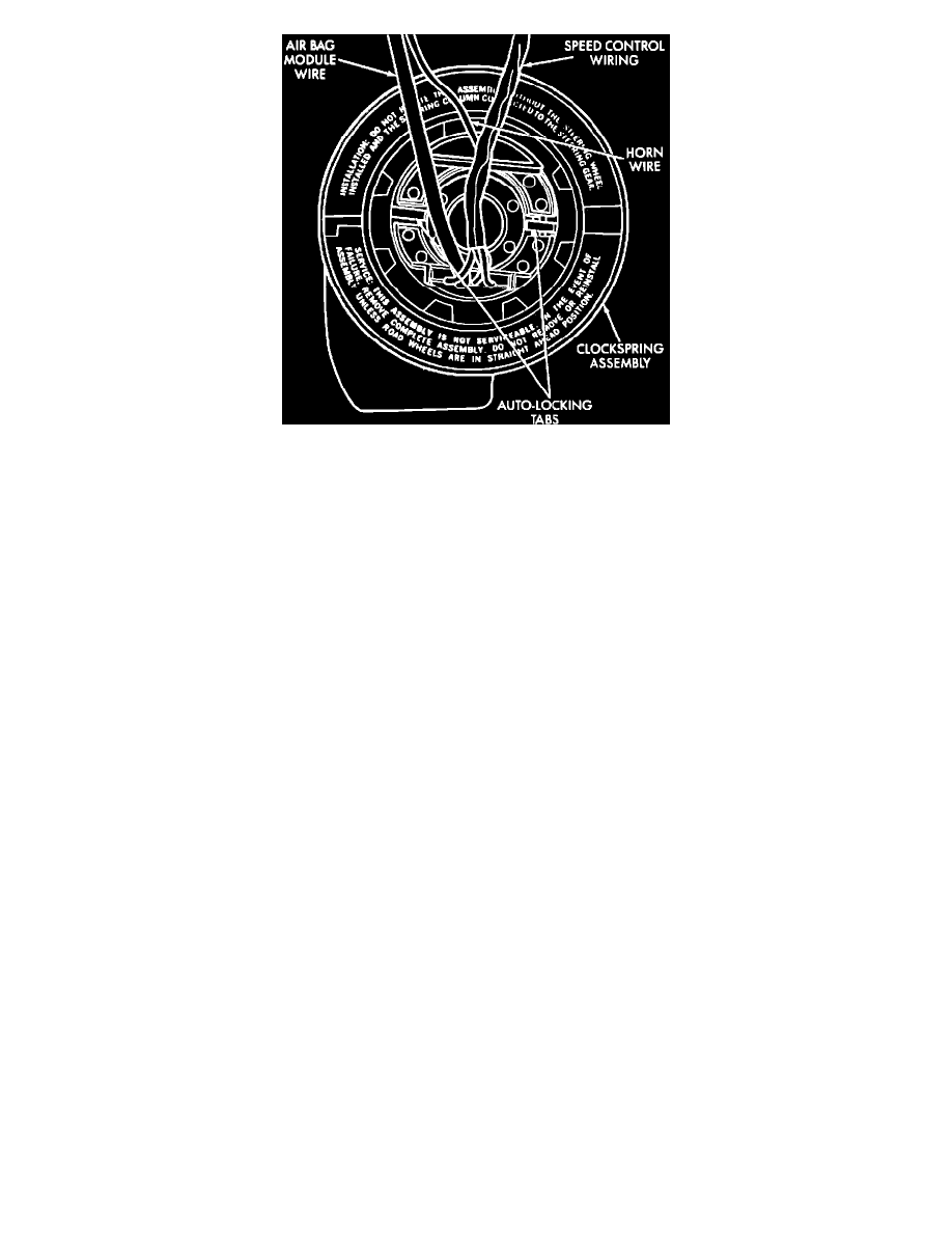
Fig. 92 Auto-Locking Type Clockspring, (Acustar Steering Column)
8.
Remove clockspring by lifting locating tabs as necessary.
CENTERING
1.
Place front wheels in straight ahead position.
2.
Depress two plastic locking pins or spread apart two metal locking tabs in center of clockspring.
3.
At the same time, rotate clockspring rotor clockwise to the end of its travel.
4.
From this position, rotate clockspring rotor counterclockwise 2 1/2 turns. The horn wire should be at the top and the squib wire at the bottom.
While turning the rotor, visually inspect flat cable for bends or kinks. If clockspring is bent or kinked, replace clockspring assembly.
INSTALLATION
1.
Snap clockspring onto steering column. Ensure clockspring is centered, if not follow clockspring centering procedure.
2.
Connect clockspring assembly to instrument panel wiring harness, ensure wiring locator clips are properly seated on outside of wiring trough and
locking tabs are engaged.
3.
Install steering column shrouds, ensure wire is inside shroud.
4.
Ensure front wheels are in straight ahead position. Install steering wheel and vibration dampner, if equipped. Torque to 45 lb-ft. Fit flats on hub of
steering wheel with formations on inside of clockspring.
5.
Pull horn lead through upper smaller hole and clockspring lead through bottom larger hole.
6.
Connect horn lead wire, then airbag lead wire to airbag module. To assure complete connections, latching arms must be visible on top of connector
housing.
7.
Install airbag module, torque nuts to 80 to 100 lb-in.
8.
Do not connect negative battery cable. Refer to Air Bag Systems/Testing and Inspection/Procedures for proper procedure.