
Sundance L4-153 2.5L SOHC VIN K TBI (1992)
Oxygen Sensor: Testing and Inspection
Powertrain Control Module Response Test
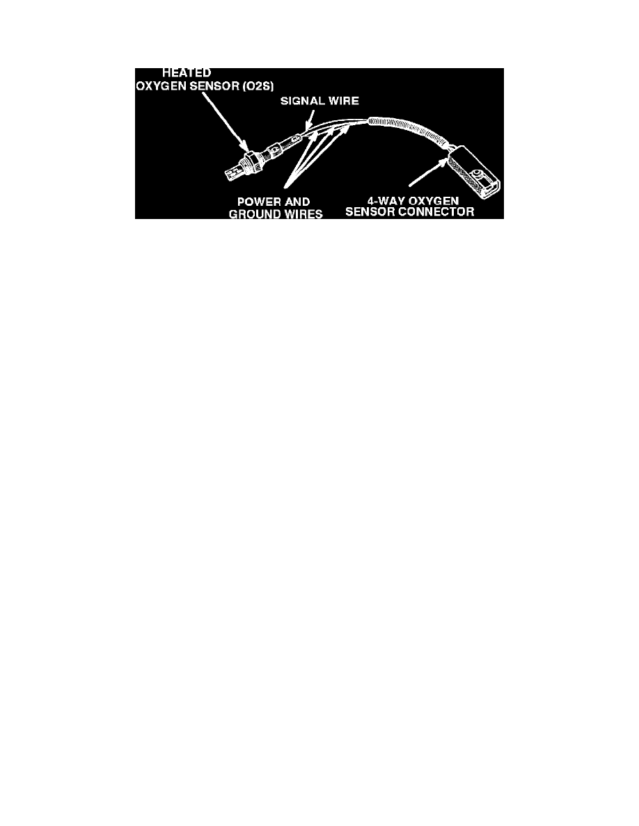
Oxygen Sensor And Connector
Note:
This test should be performed only after the Oxygen Sensor (HO2S) has passed the Sensor Functional Test and Sensor Heating Element Test
.
Note:
A four gas analyzer is needed to perform this test.
Note: When performing this test it is important that no part of your body contact the vehicle body, as test results will be inaccurate.
Caution: NEVER apply voltage directly to any computer sensor wire, unless directed to do so by a test procedure.
Preparation:
1.
Run the engine at 2500 rpm for 3 minutes with the transmission in PARK (A/T) or NEUTRAL (M/T), (to ensure vehicle and O2 sensor are at
operating temperature and vehicle is in closed loop).
2.
Turn engine OFF, disconnect the O2 sensor connector. Connect one end of a jumper wire to the harness side O2 sensor signal wire.
3.
Start the engine and run at 2500 rpm for 1 minute, with the transmission in PARK (A/T), or NEUTRAL (M/T).
4.
Let engine idle.
Lean Mixture Simulation (PCM Should Attempt To Enrich Mixture)
1.
Hold the open end of the jumper wire in one hand, and touch the other hand to battery negative, hold for 10 to 20 seconds.
^ The CO and HC readings should increase as the PCM attempts to enrich the mixture, by increasing injector pulse width.
2.
If the readings do not change as described, further testing of the oxygen sensor circuit and/or engine control system will be necessary. SEE
Powertrain Management/Computers and Control Systems/Testing and Inspection/Procedures.
Rich Mixture Simulation (PCM Should Attempt To Lean Out Mixture)
1.
Hold the open end of the jumper wire in one hand, and touch the other hand to battery positive, hold for 10 to 20 seconds.
^ The O2 readings should begin to increase, and the CO reading should decrease.
2.
If the readings do not change as described, further testing of the oxygen sensor circuit and/or engine control system will be necessary. SEE
Diagnostic Charts/ No Fault Tests.