
Sundance V6-181 3.0L SOHC (1994)
shaft and reinstall damper weight.
5. On all units, remove circlip from shaft groove and discard.
Fig.11 Outer C/V Joint Circlip Removal
6. On GKN units, do not remove heavy lock ring from shaft, unless shaft requires replacement.
7. On all units, if constant velocity joint was operating satisfactorily and grease does not appear contaminated, proceed to "Assembly" procedure,
Step 8.
8. If constant velocity joint is noisy or badly worn, replace entire unit. The repair kit will include boot, clamps, circlip and lubricant. Clean and
inspect joint as outlined in the following steps.
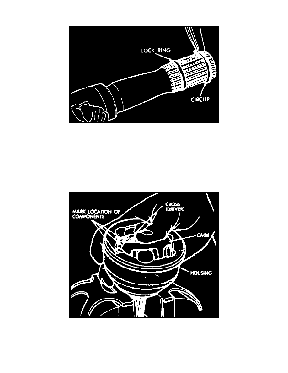
9. Clean surplus grease and mark relative position of inner cross, cage and housing with a dab of paint.
10. Hold joint vertically in a soft jawed vise.
11. Press downward on one side of inner race to tilt cage and remove ball from opposite side. If joint is tight, use a hammer and a brass drift to tap
inner race. Do not strike cage. Repeat this step until all six balls are removed. A screwdriver may be used to pry balls loose.
Fig.12 Outer C/V Joint Ball Removal
12. Tilt cage assembly vertically and position two opposing, elongated cage windows in area between ball grooves. Remove cage and inner race
assembly by pulling upward from housing.