
Sundance Duster L4-153 2.5L VIN K FI (1992)
1. Position power brake unit on vehicle.
2. Install and torque mounting nuts to 28 Nm (250 in. lbs.)
3. Using lubriplate or equivalent coat the bearing surface of the pedal pin.
4. Connect push rod to pedal pin and install new retainer clip.
5. Carefully position master cylinder on power brake unit and torque mounting nuts to 28 Nm (250 in. lbs.).
6. Connect vacuum hose. Make sure all hose clips are reinstalled and the vacuum hoses are not kinked during reinstallation.
7. Install brake tubes between master cylinder and valve assembly, torque to 16 Nm (145 in. lbs.).
8. Move wiring harness to the original position and attach to the strut tower.
9. Install clutch cable mounting bracket (manual transmission vehicles)
10. Bleed brakes, make sure fluid level in master cylinder is maintained. Check stop light operation.
CAUTION: Do not attempt to disassemble power brake unit as this booster is serviced as a complete assembly only
PUSHROD ADJUSTMENT
Proper adjustment of the master cylinder pushrod is necessary to ensure proper operation of the power brake system. A pushrod that is too long will
cause the master cylinder piston to close off the compensating port, preventing hydraulic pressure from being released and resulting in brake drag. A
push rod that is too short will cause excessive brake pedal travel and cause groaning noises to come from the booster when the brakes are applied. A
properly adjusted pushrod that remains assembled to the booster with which is was matched during production should not require service adjustment.
However, if the booster, master cylinder or pushrod are serviced, the pushrod may require adjustment. There are two methods that can be used to
check for proper push rod length and installation: the gauge method and air method. Usually, if the power unit push rod requires an adjustment the
Power Unit Repair Kit for the unit being serviced includes a gauge. The gauge measures from the end of the push rod to the power unit shell.
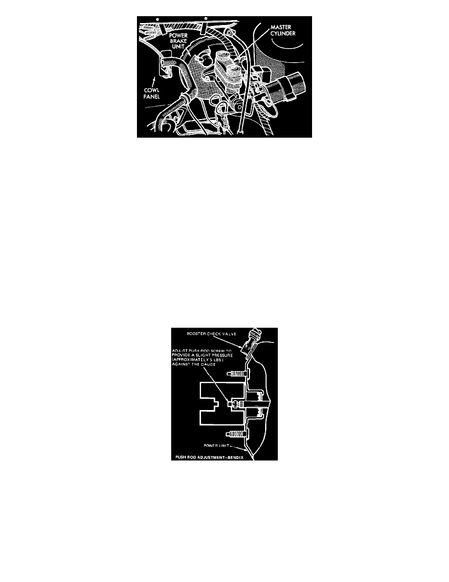
Fig. 1 Master cylinder push rod adjustment. Bendix type vacuum booster
GAUGE METHOD
BENDIX TYPE
1.
Disconnect master cylinder from booster leaving brake lines connected, and secure cylinder to prevent lines from being damaged.
2.
Start engine and allow to run at normal curb idle speed.
3.
With engine running, position gauge over pushrod. Gauge should and bottom against booster housing with a force of approximately 5 lbs. applied
to push rod.
4.
If force required to seat gauge exceeds 5 lb., shorten length of pushrod. If force required to seat gauge is less than 5 lbs, lengthen push rod. Ensure
that pushrod is properly seated in booster when performing gauge check.
5.
Reinstall master cylinder and remove reservoir cover.