
Turismo L4-105 1720cc 1.7L VIN B 2-bbl (1983)
Valve Clearance: Adjustments
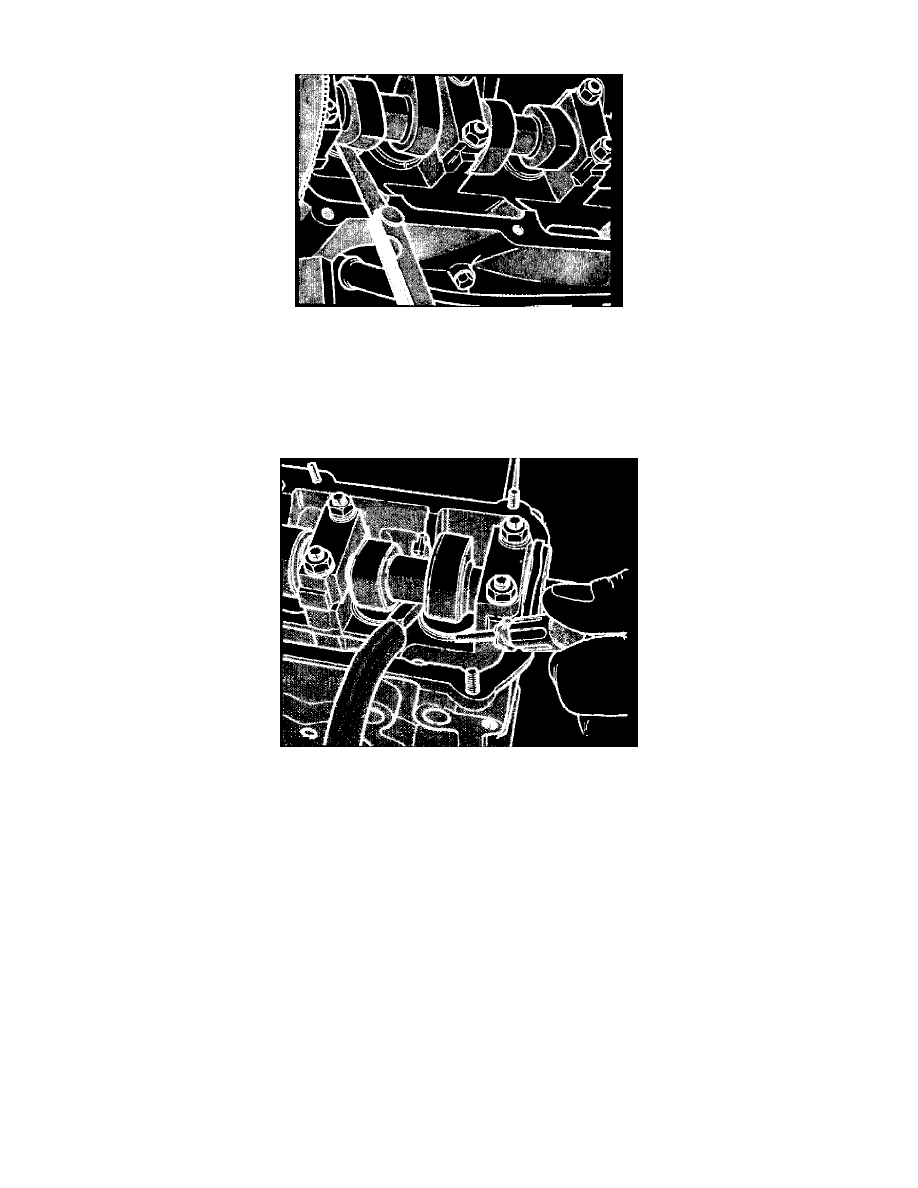
Fig. 8 Checking valve clearance
1.
Using feeler gauges, check valve clearance with cam lobe in position shown in Fig. 8. Engine should be at normal operating temperature, with
thermostat open and coolant temperature approximately 195°F. If necessary to check valve clearance with cylinder head cold, use following
specifications: Intake, .006 - .010 inch; Exhaust, .014 - .018 inch, then recheck after engine has reached normal operating temperature.
2.
If valve clearance is greater than specified, remove valve adjusting disc and insert a thicker disc to obtain proper clearance.
3.
If valve clearance is less than specified, remove valve adjusting disc and insert a thinner disc to obtain proper clearance.
Fig. 9 Valve adjusting disc replacement
4.
To replace valve adjusting disc, depress cam follower with tool L-4417 or equivalent and remove with a narrow screwdriver, Fig. 9, and a magnet.
Install new disc and recheck clearance.
5.
Valve adjusting discs are available in thicknesses of 3.00 mm to 4.25 mm in increments of .05 mm.