
Voyager L4-135 2.2L SOHC (1985)
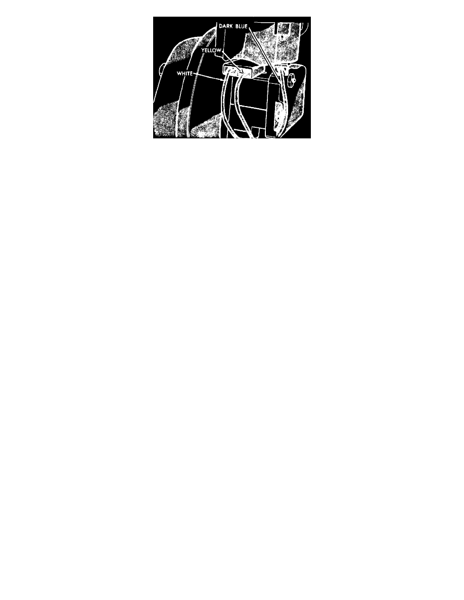
Fig. 14 Servo terminals, front wheel drive models
1983-85 FRONT WHEEL DRIVE MODELS
1. Connect a suitable test lamp between brown wire with red tracer and ground then proceed as follows:
a. Place speed control switch and ignition switch in "On" position. Test lamp should illuminate.
b. Depress "Set" button. Test lamp should go out and a clicking noise should be heard at servo.
c. Release "Set" button. Test lamp should illuminate and another click should be heard at servo.
d. If test results are not satisfactory, possible causes may be a blown fuse, faulty wiring or a defective speed control switch or servo.
2. Connect a suitable test lamp between white wire with red tracer and ground then proceed as follows:
a. Place speed control switch and ignition switch in "On" position. Test lamp should be off.
b. Depress "Set" button. Test lamp should illuminate.
c. If test results are not satisfactory, possible causes may be faulty wiring or a defective speed control switch.
3. Connect a suitable test lamp between blue wire with red tracer and ground then proceed as follows:
a. Place speed control switch and ignition switch in "On" position. Test lamp should illuminate.
b. If test result is not satisfactory, possible causes may be faulty wiring or defective brake, clutch, or speed control switches.