
Voyager L4-135 2.2L SOHC (1985)
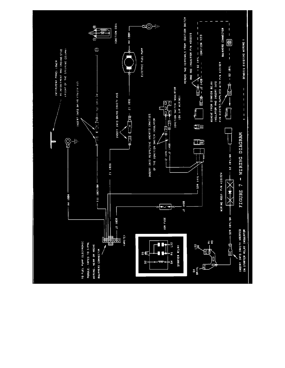
FIGURE 7 - WIRING DIAGRAM
3.
Disconnect the 5-way ignition switch connector and remove the yellow wire (Figures 2-C - steering column may need to be lowered to gain
access). Install the yellow wire just removed, into the top half of the natural colored 2-way female connector supplied with the instrument
panel overlay harness, PN 4331574.
NOTE:
YELLOW WIRE IN FEMALE CONNECTOR MUST LINE UP WITH YELLOW WIRE IN MALE CONNECTOR OF
OVERLAY HARNESS, PN 4331574 (FIGURES 2-C AND 7).
Install the bare terminal yellow wire of the instrument panel overlay harness, PN 4331574, into the previously vacated cavity in the ignition switch
connector (Figures 2-C and 7).
4.
Remove the dark blue wire from the 5-way ignition switch connector and install into the bottom half of the natural colored 2-way female connector