
Voyager L4-135 2.2L SOHC (1985)
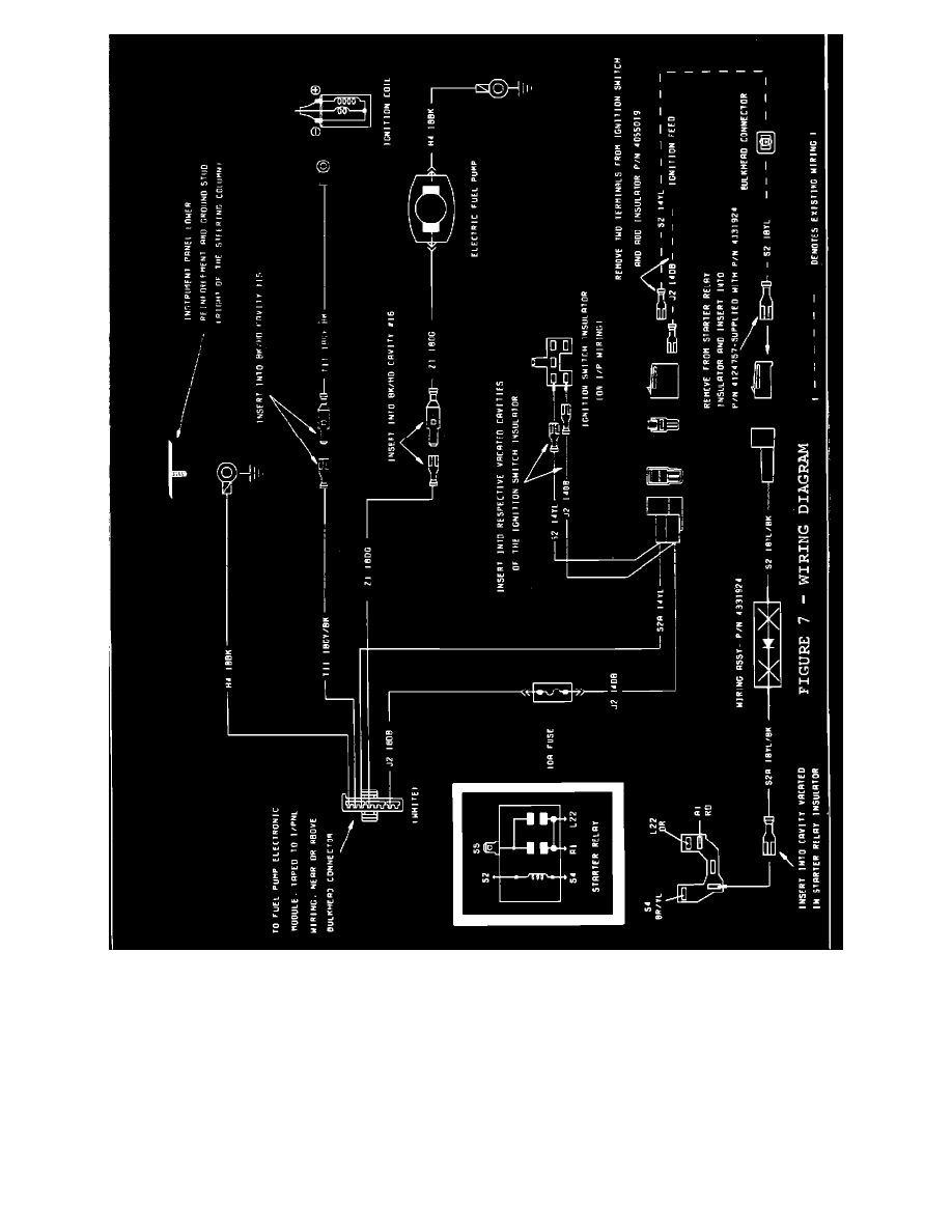
FIGURE 7 - WIRING DIAGRAM
6.
Remove the large 5-way connector on the starter relay and extract the yellow wire (S-2 circuit - note position of wire in connector). On Diode
Wire Jumper, PN 4331924, remove the loose insulator from the yellow with black tracer wire. Reset tang and snap the bare terminal of
yellow wire (S-2 circuit) removed from the starter relay into the loose insulator from Diode Wire Jumper, PN 4331924. Mate male connector
on Diode Wire Jumper, PN 4331924, with female connector now on yellow wire (S-2 circuit) from starter relay (Figure 7).
7.
Insert bare female terminal wire (yellow with black tracer) of Diode Wire Jumper Harness, PN 4331924, into starter relay connector (same
cavity from which S-2 yellow wire was extracted in Step 6, Figure 7).