
Voyager L4-135 2.2L SOHC (1985)
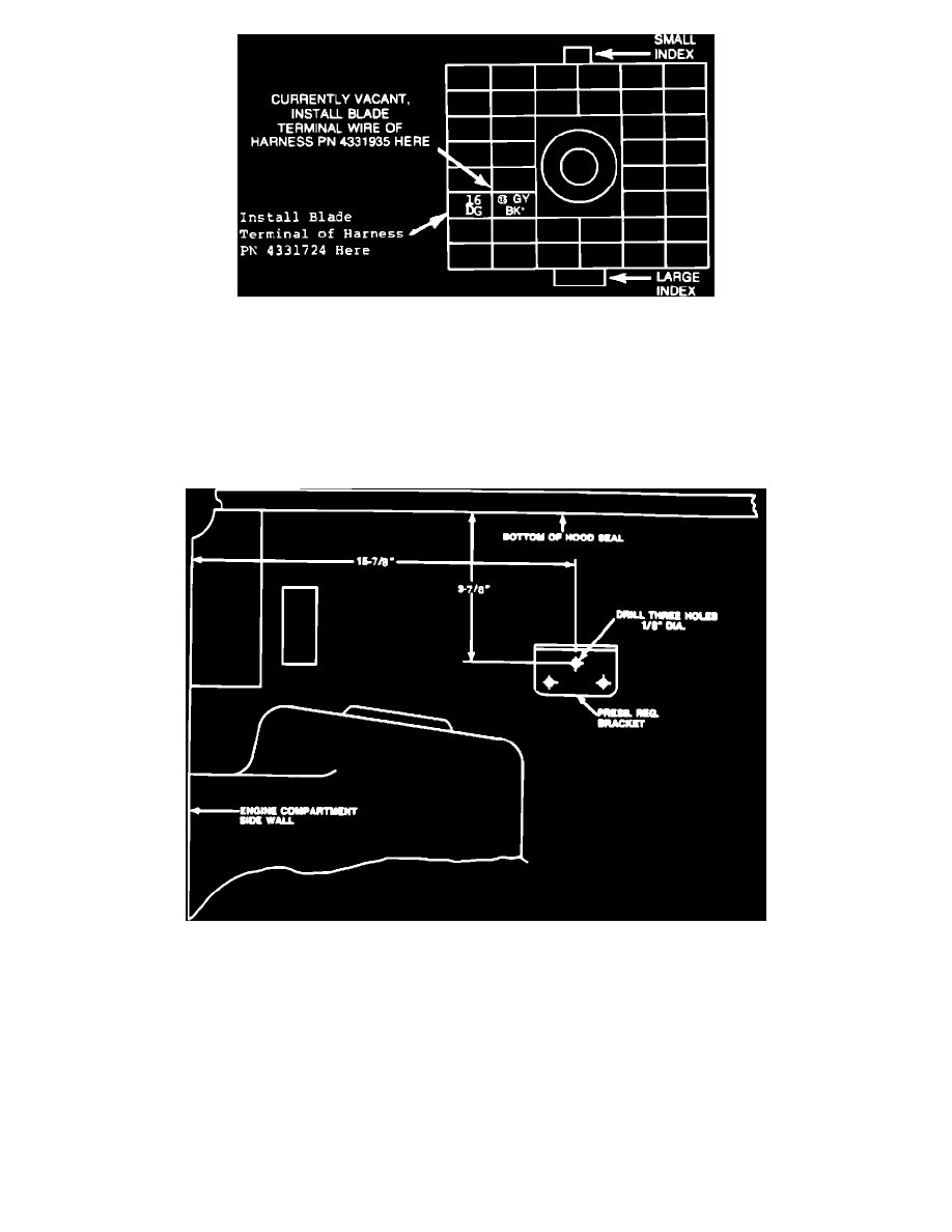
FIGURE 1-D - TERMINAL END OF BULKHEAD CONNECTOR (ENGINE COMPARTMENT SIDE)
4.
At the engine compartment route the harness through the speedometer cable clips to the bulkhead connector.
5.
Coat the bare blade terminal of the body harness, PN 4331724, liberally with Mopar Multi-Purpose Grease, PN 4318063, and snap into
cavity #16 of the engine side of the bulkhead connector (Figure 1-D). Fill unsealed cavities above cavity #16 with Multi-Purpose Grease, PN
4318063.
6.
Reinstall instrument panel half, then engine compartment half of bulkhead connector. Torque to 40 inch pounds. 18-13-85-5-
FIGURE 4 - PRESSURE REGULATOR BRACKET INSTALLATION
E.
Engine Compartment Fuel Component Installation
1.
On the right side of the dash panel mark the location of the pressure regulator bracket top attaching hole as shown in Figure 4. Center punch
and drill a 1/8" diameter hole and attach pressure regulator bracket, PN 4306972, with selftapping screw, PN 6031991. (Position the bracket
so its top surface is horizontal and tighten screw securely.) Drill 1/8" diameter holes in the center of the two lower bracket holes. Install the
remaining two screws, PN 6031991, and tighten securely.