
Voyager L4-135 2.2L SOHC (1985)
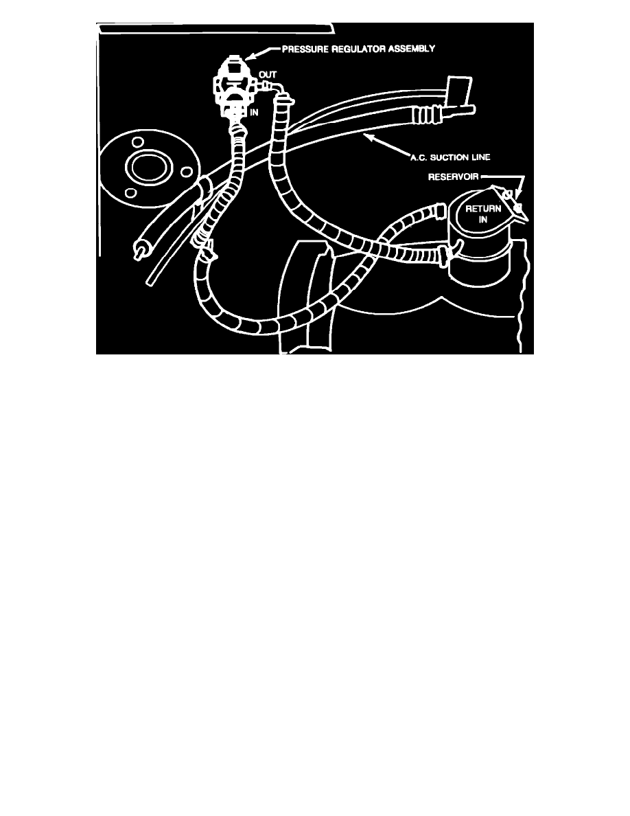
FIGURE 6 - HOSE ROUTING & UNDERHOOD COMPONENT LOCATION
7.
Attach the fuel reservoir/filter assembly, PN 4288337, to the bracket with two nuts, PN 6100047.
8.
Connect the 5/16" fuel supply hose assembly, PN 4203866, from the chassis fuel supply line to the pressure regulator inlet (Figure 6). Secure the
hose with hose clamp, PN 6000651, and torque to 10 inch pounds.
9.
Install fuel supply hose assembly, PN 4203837, from the pressure regulator outlet to the fuel reservoir inlet. Secure with hose clamp, PN 6500651,
and torque to 10 inch pounds.
10.
Install the vapor return hose assembly, PN 4203860, from the reservoir return nipple to the chassis vapor return line. Secure with hose clamp, PN
6500650, and torque to 10 inch pounds.
11.
Connect the hose on the reservoir outlet (bottom) to the carburetor inlet. Secure with hose clamp, PN 6500651, and torque to 10 inch pounds.
12.
Reconnect battery.