
Voyager L4-135 2.2L SOHC (1985)
of overlay harness (opposite the dark blue wire in male half of overlay harness, PN 4331574). Install the bare terminal dark blue wire from overlay
harness into previously vacated cavity in ignition switch connector (Figures 2-C and 7).
5.
Reconnect the natural colored 2-way connectors supplied with the instrument panel overlay harness and reconnect the ignition switch connector.
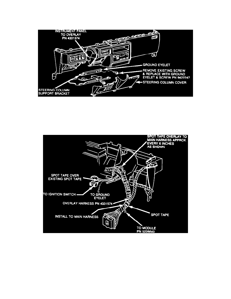
FIGURE 2-A
6.
Remove the far right-hand screw from the lower reinforcement steering column support bracket. Secure bare eyelet ground terminal (black wire)
from the instrument panel overlay harness, PN 4331574, to the steering column support bracket using screw, PN 9422247 (Figure 2-A). Tighten
securely.
7.
Connect the control module, PN 5226640, to the white 8-way connector from the instrument panel overlay harness.
FIGURE 2-D - INSTRUMENT PANEL WIRING