
Voyager L4-135 2.2L SOHC (1985)
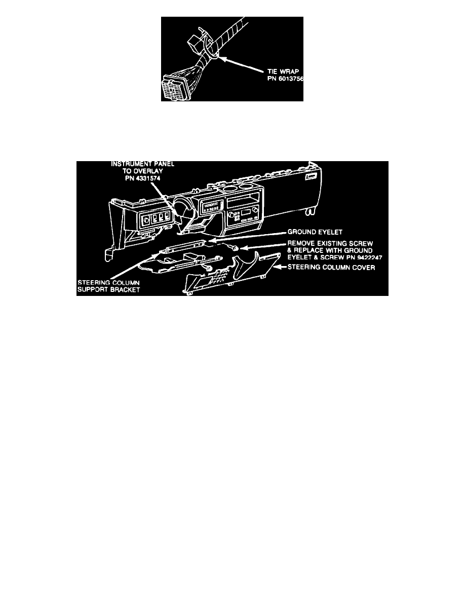
FIGURE 2-E - TYPICAL CONTROL MODULE MOUNTING
8.
Route the instrument panel harness and module to keep them clear of any possible interferences. Spot tape the overlay harness to the main harness
every six inches as shown in Figure 2-D. Secure the control module to the main harness with a tie wrap, PN 6015756, close to the bulkhead
connector as shown in Figure 2-E.
FIGURE 2-A
9.
Replace the steering column lower silencer and cover (Figure 2-A).
C.
In-Tank Fuel Gauge Pump Unit Assembly Installation
1.
Refer to the service manual procedure for removing fuel tank sending unit.
2.
Install seal, PN 6031475, on the new gauge/pump unit, PN 4075479*, (15 gallon tank) or 4075480* (20 gallon tank). Using extreme caution
to protect the float and gauge assembly, install new gauge/pump unit in the fuel tank.
3.
Refer to the service manual procedure for the balance of the installation of the fuel tank sending unit.
4.
Install the 3-terminal fuel gauge connector to the gauge/pump unit.
D.
Body Wiring Harness PN 4331724
1.
Insert the mold of body harness, PN 4331724, onto the stud of the fuel tank gauge/pump unit.
*Revised Part Number TSB 18-37-86 Revised December 8, 1986