
Voyager V6-181 3.0L SOHC (1988)
2.
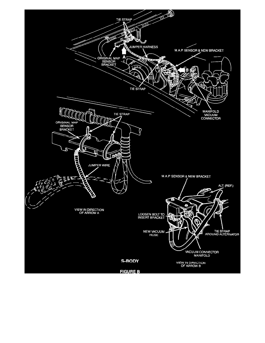
Remove the map sensor from the bracket at its present location (right shock tower on the C-body and on the dash panel behind the engine on the
S-body). Disconnect the electrical connector and vacuum line connected to the map sensor. Remove and discard the map sensor bracket on the
C-body, but do not remove bracket on the S-body.
3.
Install the new map sensor bracket by loosening the bolt located on the front of the alternator bracket and slipping the new map sensor bracket
behind the bolt head. Tighten the bolt to 220 in.lbs. (see illustrations).
4.
Install the map sensor on the new map sensor bracket using the original screws.
5.
Remove and discard the existing vacuum line assembly serving the old map sensor location. Using the new vacuum hose supplied, connect it
between the vacuum nipple on the intake manifold and nipple of the map sensor (see illustration).