
Voyager V6-181 3.0L SOHC (1988)
Engine Control Module: Description and Operation
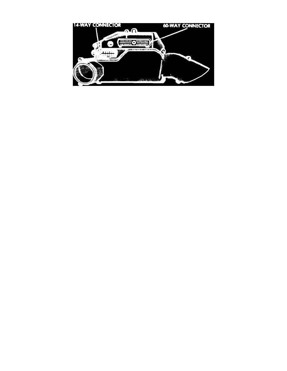
Fig. 2 Single Module Engine Controller (SMEC)
The SMEC, Fig. 2, is mounted in the engine compartment and contains circuits necessary to energize the ignition coil, fuel injectors and alternator
field in order to minimize electrical noise in the passenger compartment. The SMEC contains a voltage converter which converts battery voltage into a
regulated 8 volt output to energize the ignition pick up coil. The externally mounted Automatic Shut Down (ASD) relay which interrupts power to the
fuel pump, ignition coil and injector when necessary is controlled by the SMEC.
The ASD relay is turned on and off by the SMEC in response to distributor reference pulses. When distributor reference pulses are transmitted to the
SMEC, the SMEC activates the ASD relay. However, when no reference pulse is transmitted to the SMEC, the ASD relay is deactivated and power is
shut off to the fuel control system and ignition coil.
The SMEC has been programmed to monitor several different circuits of the fuel injection system in order to provide a self-diagnosis function. In
conjunction with the self-diagnosis function, a check engine lamp is wired into the system to indicate a failure in the monitored circuits. The check
engine lamp is illuminated for 3 seconds whenever the engine is started as a `bulb test.' However, if the SMEC detects a malfunction in one of the
monitored circuits the check engine lamp will be illuminated and will remain on as long as the ignition key remains in the on position. Illumination of the
check engine lamp indicates that the system has entered the `limp-in' mode and signals an immediate need for system service.
If vehicle performance or the check engine lamp indicate fuel injection system malfunctions, certain procedures should be followed. Prior to
suspecting the fuel injection service as the cause for complaints, ensure that the engine and all related systems are in proper operating condition. After
checking related systems, inspect fuel injection components and connecting harnesses as outlined in Visual Inspection, repair system as indicated, then
road test vehicle to check system operation. If service performed during visual inspection does not correct observed malfunctions, or if check engine
lamp remains illuminated, refer to `Obtaining fault codes' to call up fault codes stored in the SMEC memory and correct as needed.
If a problem is sensed by the SMEC often enough to be considered a malfunction, it is stored in the SMEC memory in the form of a fault code. If the
problem is repaired, or ceases to occur, the SMEC will cancel the code after 20---40 engine cycles.
Fault codes can be called up and displayed either by observing flashes of the check engine lamp or by using diagnostic tool C-4805 on 1987 models
and the Diagnostic Readout Box II (DRB II) on 1988 models, referring to the usage procedures as outlined for the desired method.