
Voyager V6-201 3.3L VIN R SMFI (1997)
HCU To Suspension Cradle Mounting Bolts
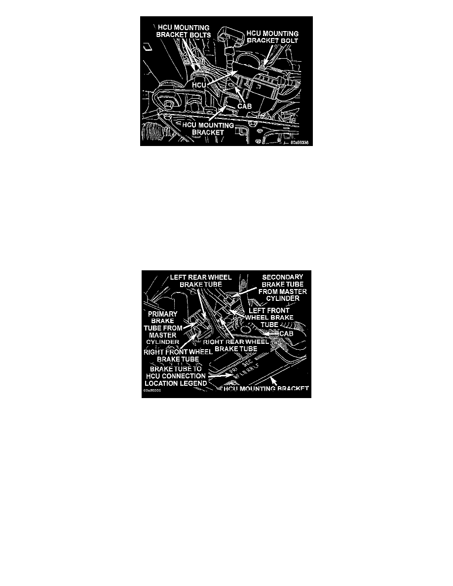
3. Install the HCU and its mounting bracket as an assembly on the front suspension crossmember. Install the 3 bolts attaching the HCU bracket to the
crossmember. Tighten the 3 mounting bolts to a torque of 28 Nm (250 inch lbs.).
CAUTION: Because of the flexible section in the primary and secondary brake tubes, and the brake tubes between the HCU and the
proportioning valve, the brake tubes must be held in proper orientation when tightened and torqued. These tubes must not contact each other or
other vehicle components when installed.
CAUTION: When installing the chassis brake tubes on the HCU valve block, they must be located correctly in the valve block to ensure proper
ABS operation. Refer to above image for the correct chassis brake tube locations.
NOTE: The chassis brake tube attachment locations to the HCU, are marked on the bottom of the HCU mounting bracket.
Brake Tube Connections To HCU
4. Install the 6 chassis brake tubes into their correct port locations on the HCU valve block as shown above. Tighten the tube nuts to a torque of 17
Nm (145 inch lbs.).
NOTE: Before installing the 25 way connector in the CAB be sure the seal is properly installed in the connector.