
Voyager V6-201 3.3L VIN R SMFI (1997)
1/2 inch from each edge of the hole across the counterweight face (Figure 4).
8.
Center punch a mark at either the 1 inch or 1/2 inch marks at one half the thickness of the counterweight.
9.
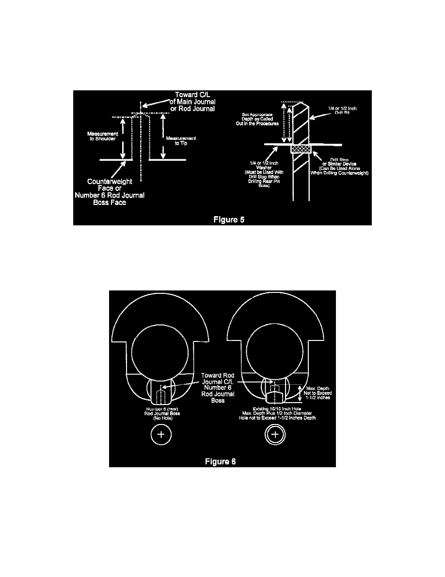
Drill a 1/4 inch diameter pilot hole at each center punched location 13/16 inch deep as measured to the drill tip location (Figure 5). Each hole must
be drilled perpendicular to the cast surface or towards the centerline of the main journal (Figure 4).
10.
Using a 1/2 inch diameter bit, enlarge the pilot holes to the same depth listed above.
CAUTION:
THIS DRILLING OPERATION IS CRITICAL AND MUST BE PERFORMED PROPERLY. USE A DRILL STOP OR SIMILAR MEANS TO
PREVENT EXCESS MATERIAL REMOVAL (FIGURE 5).
CAUTION:
USE SAFETY GOGGLES AND PROTECTIVE CLOTHING WHILE PERFORMING THIS DRILLING OPERATION.
11.
Inspect the rear rod journal boss. There will either be no hole, or a 15/16 inch diameter hole drilled to varying depths (Figure 6). Perform one of
the following procedures depending on your rod journal boss inspection:
NO HOLE
A.
Locate the center point of the boss and make a center punch mark.
B.
Drill a 1/4 inch diameter pilot hole at the center punched location 3/4 inch deep as measured to the drill tip location. The hole must be
drilled perpendicular to the cast surface or towards the centerline of the rod journal (Figure 6).