
Voyager V6-201 3.3L VIN R SMFI (1997)
Instrument Panel Circuit Board: Service and Repair
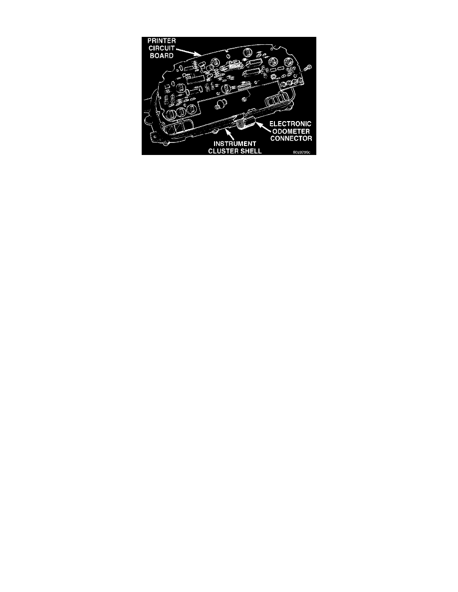
Instrument Cluster Printed Circuit Board
REMOVAL
1. Remove the instrument cluster.
2. Remove the instrument cluster back panel.
3. Disconnect the electronic cluster wire connector from the printed circuit board.
4. Remove the screws holding wire connector insulator to the instrument cluster shell and the printed circuit board.
5. Remove the screws holding printed circuit board to the cluster shell.
6. Remove the printed circuit board from the cluster.
INSTALLATION
1. Remove the printed circuit board from the cluster.
2. Remove the screws holding printed circuit board to the cluster shell.
3. Remove the screws holding wire connector insulator to the instrument cluster shell and the printed circuit board.
4. Disconnect the electronic cluster wire connector from the printed circuit board.
5. Remove the instrument cluster back panel.
6. Remove the instrument cluster.
After installing the print circuit board it will have to be calibrated using a scan tool (DRB III).
NOTE: Speedometer and/or Tachometer will not operate properly until all gauges have been calibrated.