
Voyager V6-229 3.8L (1996)
4.
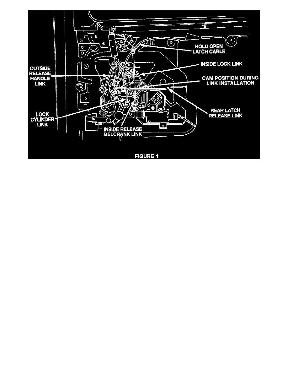
with the sliding door ajar, disengage the clip holding the rear latch release link to the latch/lock control, refer to Figure 1, and separate the link
from the control.
5.
Disengage the clip holding the outside door handle link to the latch/lock control.
6.
Disengage the clip holding the inside release bellcrank link to the latch/lock control.
7.
Disengage the clip holding the lock cylinder link to the latch/lock control and separate the lock cylinder link from the latch/lock control.
8.
Disengage the hold open latch cable ball end from the latch/lock control and disengage the lock tabs holding the hold open latch cable case to the
latch/lock control.
9.
Loosen the bolts holding the latch/lock control to the sliding door.
10.
Disengage the wire connector from the power door lock motor.
11.
Separate the latch/lock from the vehicle.
12.
Remove the screws attaching the power lock motor to the latch lock control and separate the motor from the control.
13.
Install the new sliding door power lock motor (P/N 4675782) by reversing the previous steps.
NOTE:
PLACE THE CLIP FOR THE OUTSIDE RELEASE HANDLE LINK ATTHE BOTTOM OF THE SLOT BEFORE INSERTING THE LINK.
PLACE THE CLIP FOR THE INSIDE RELEASE BELLCRANK LINK AT THE TOP OF THE SLOT BEFORE INSERTING THE LINK. PUSH
THE REAR LATCH RELEASE LINK TO ITS FULL REARWARD POSITION BEFORE INSERTING IT INTO ITS CLIP ON THE
LATCH/LOCK CONTROL.
14.
Repeat steps 1 thru 13 for the other sliding door if required.
NOTE:
IF INTERMITTENT SLIDING DOOR POWER LOCK OPERATION EXISTS, REFER TO TECHNICAL SERVICE BULLETIN 08-40-95.
Liftgate Procedure
LIFTGATE PROCEDURE