
Voyager V6-3.0L VIN 3 (1998)
Hydraulic Control Assembly - Antilock Brakes: Description and Operation
General Information
Teves Mark 20 ICU
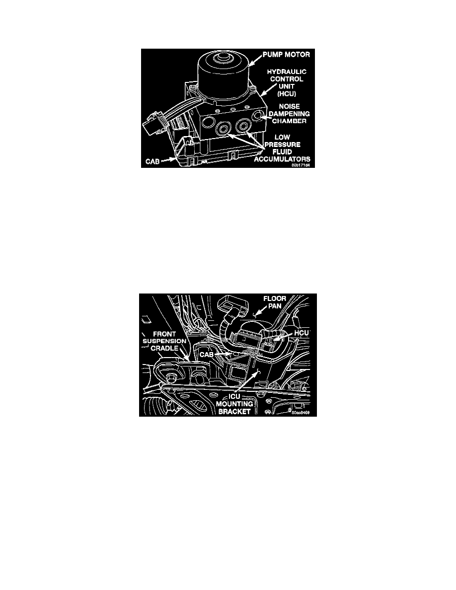
The Hydraulic Control Unit (HCU) used with the Teves Mark 20 ABS is different from the HCU used on previous Chrysler products with ABS. The
HCU used on this ABS system is part of the Integrated Control Unit (ICU). The HCU is part of what is referred to as the ICU because the HCU and the
Controller Antilock Brakes (CAB) are combined (integrated) into one unit. This differs from previous Chrysler products with ABS, where the HCU and
the CAB were separate components located in different areas of the vehicle.
Teves Mark 20 ABS uses two different HCU's and CAB's depending on the type of ABS system the vehicle is equipped with. There is a unique HCU
and CAB for a vehicle equipped with just ABS and a unique HCU and CAB for a vehicle equipped with ABS and traction control.
NOTE: The HCU and CAB used on a vehicle that is equipped with only ABS and on a vehicle that is equipped with ABS and traction control are
different. The HCU on a vehicle equipped with ABS and traction control has a valve block housing that is approximately 1 inch longer on the low
pressure fluid accumulators side than a HCU for a vehicle that is equipped with only ABS.
ICU Mounting Location
The ICU is located on the driver's side of the vehicle, and is mounted to the front suspension cradle. The ABS only ICU contains the following
components for controlling the brake system hydraulic pressure during ABS braking: The CAB, eight valve solenoids, (four inlet valves and four outlet
valves) fluid accumulators a pump, and an electric motor. The ABS with traction control ICU contains the following components for controlling the
brake system hydraulic pressure during ABS braking and traction control operation: The CAB, four solenoid controlled inlet valves, four solenoid
controlled outlet valves, two hydraulic shuttle valves, two ASR valves, fluid accumulators a pump and an electric motor. Also attached to the hydraulic
control unit are the master cylinder primary and secondary brake tubes and the brake tubes going to each wheel of the vehicle.
CAUTION: No components of the ICU are serviceable. If any component that makes up the ICU is diagnosed as not functioning properly it MUST be
replaced. The replaceable components of the ICU, are the HCU and the CAB. The mounting bracket is also replaceable as a separate component of the
ICU. The remaining components of the ICU are not serviceable items. No attempt should ever be made to remove or service any individual components
of the HCU. This is due to the concern of contamination entering the HCU while performing a service procedure. Also no attempt should ever be made
to remove or service any individual components of the CAB.
CAUTION: At no time when servicing the ICU should a 12 volt power source be applied to any electrical connector of the HCU or the CAB.