
Voyager V6-3.3L VIN G Flex Fuel (2000)
Valve: Service and Repair
REMOVAL
1. With cylinder head removed, compress valve springs using Valve Spring Compressor Tool C-3422-B with adapter 6412.
2. Remove valve retaining locks, valve spring retainers, valve stem seals and valve springs.
3. Before removing valves, remove any burrs from valve stem lock grooves to prevent damage to the valve guides. Identify valves to insure
installation in original location.
VALVE INSTALLATION
1. Coat valve stems with clean engine oil and insert them in cylinder head.
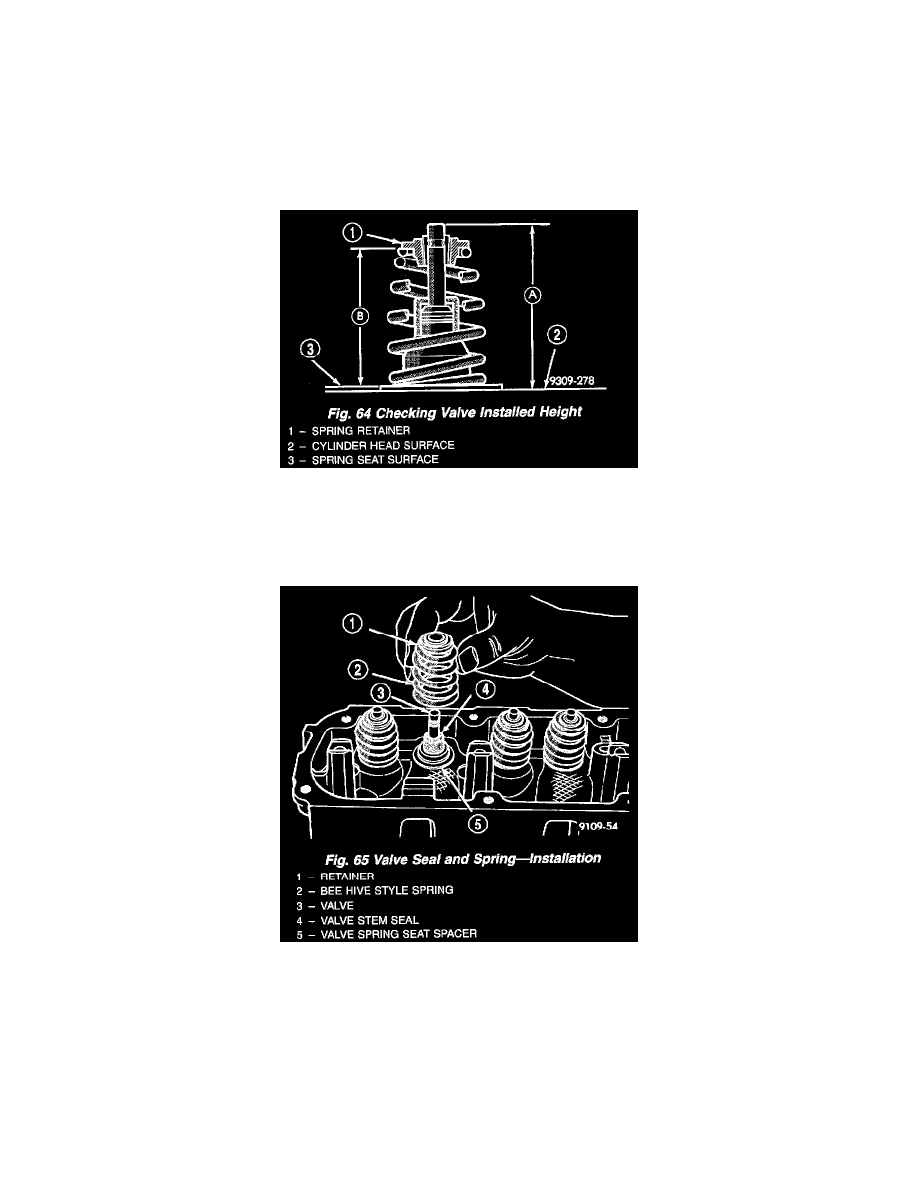
Fig. 64
2. Check valve tip to spring seat dimensions A after grinding the valve seats or faces. Grind valve tip to give 49.541 to 51.271 mm (1.950 to 2.018
inch) over spring seat when installed in the head (Fig. 64). Check valve tip for scoring, if necessary, the tip chamfer should be reground to prevent
seal damage when the valve is installed.
Fig. 65
3. Install valve spring seat spacer on head (Fig. 65).
4. Install new cup seals on all valve stems and over valve guides (Fig. 64). Install valve springs and valve retainers (Fig. 65).
5. Compress valve springs with Valve Spring Compressor Tool C-3422-B, with adapter 6412 install locks and release tool. If valves and/or seats are
reground, measure the installed height of springs dimension B. make sure measurements are taken from top of spring seat to the bottom surface of
spring retainer. If height is greater than 1-19/32 inches, (40.6 mm), install a 1/32 inch (0.794 mm) spacer in head counterbore to bring spring
height back to normal 1-17/32 to 1-19/32 inch (39.1 to 40.6 mm).