
Voyager V6-3.3L VIN G Flex Fuel (2000)
Ignition Coil: Description and Operation
WARNING: THE DIRECT IGNITION SYSTEM GENERATES APPROXIMATELY 40,000 VOLTS. PERSONAL INJURY COULD
RESULT FROM CONTACT WITH THIS SYSTEM.
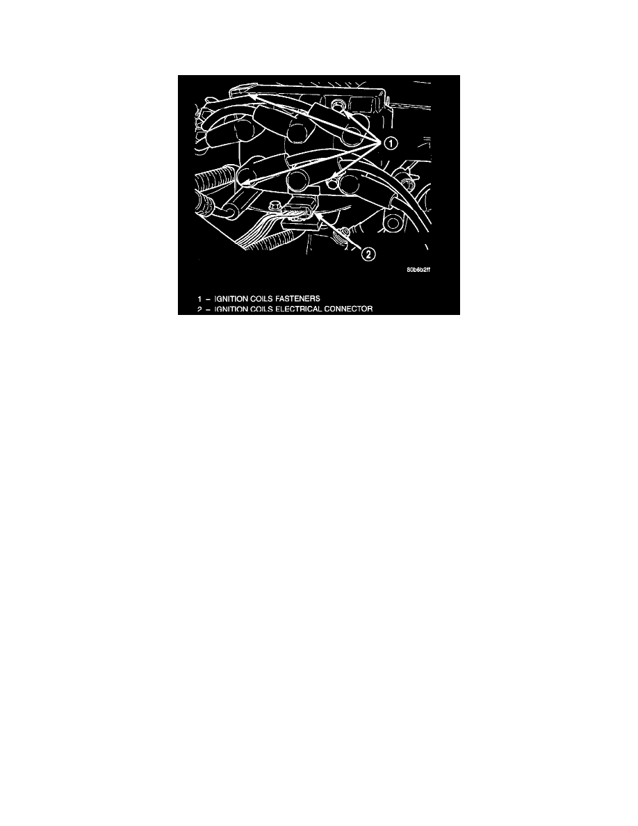
Ignition Coil Pack
The ignition coil assembly consists of 3 independent coils molded together. The coil assembly is mounted on the intake manifold. Spark plug cables
route to each cylinder from the coil.
The coil fires two spark plugs every power stroke. One plug is the cylinder under compression, the other cylinder fires on the exhaust stroke. The
Powertrain Control Module (PCM) determines which of the coils to charge and fire at the correct time.
Coil 1 fires cylinders 1 and 4, coil 2 fires cylinders 2 and 5, coil 3 fires cylinders 3 and 6.
The Auto Shutdown (ASD) relay provides battery voltage to the ignition coil. The PCM provides a ground contact (circuit) for energizing the coil. When
the PCM breaks the contact, the energy in the coil primary transfers to the secondary causing the spark. The PCM will de-energize the ASD relay if it
does not receive the crankshaft position sensor and camshaft position sensor inputs. Refer to Auto Shutdown (ASD) Relay-PCM Output, for relay
operation.