
Voyager V6-3.3L VIN G Flex Fuel (2000)
Axle Shaft: Description and Operation
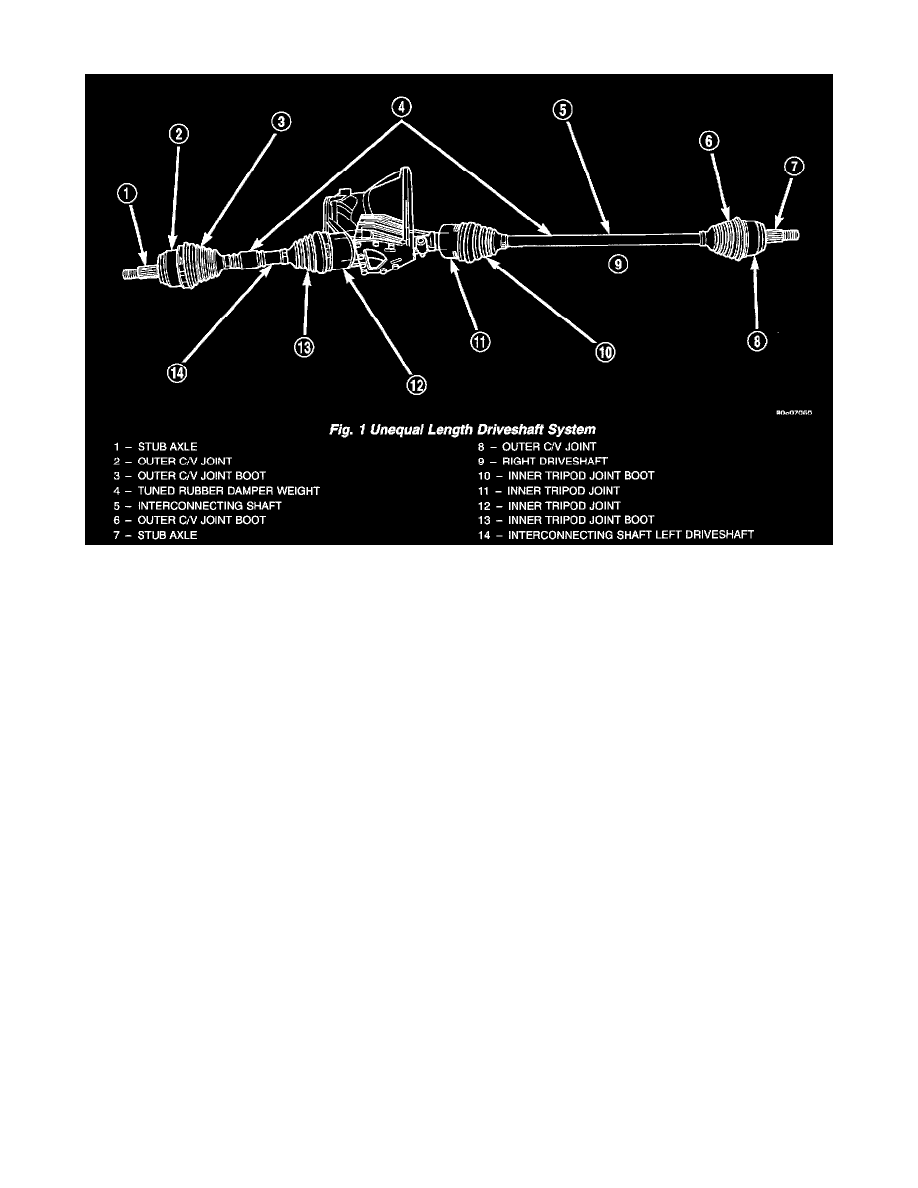
Fig. 1
Vehicles equipped with either an automatic or manual transmission uses an unequal length driveshaft system (Fig. 1).
Vehicles equipped with automatic transaxles use a solid short interconnecting shaft on the left side. The right side of the vehicle uses a longer solid
interconnecting shaft.
The left driveshaft uses a tuned rubber damper weight. When replacing the left driveshaft, be sure the replacement driveshaft has the same damper
weight as the original.
Both driveshaft assemblies use the same type of inner and outer joints. The inner joint of both driveshaft assemblies is a tripod joint, and the outer
joint of both driveshaft assemblies is a Rzeppa joint. Both tripod joints and Rzeppa joints are true constant velocity (C/V) joint assemblies. The inner
tripod joint allows for the changes in driveshaft length through the jounce and rebound travel of the front suspension.
On vehicles equipped with ABS brakes, the outer C/V joint is equipped with a tone wheel used to determine vehicle speed for ABS brake operation.
The inner tripod joint of both driveshafts is splined into the transaxle side gears. The inner tripod joints are retained in the side gears of the transaxle
using a snap ring located in the stub shaft of the tripod joint. The outer CV joint has a stub shaft that is splined into the wheel hub and retained by a
steel hub nut.
NOTE: This vehicle does not use a rubber lip bearing seal as on past front wheel drive cars, to prevent contamination of the front wheel bearing. It is
important though to thoroughly clean the outer CV joint and the wheel bearing area in the steering knuckle before it is assembled after servicing.