
Voyager V6-3.3L VIN R (1999)
Powertrain Control Module: Description and Operation
OPERATION
Powertrain Control Module
The ignition system is regulated by the Powertrain Control Module (PCM). The PCM supplies battery voltage to the ignition coil through the
Auto Shutdown (ASD) Relay. The PCM also controls ground circuit for the ignition coil. By switching the ground path for the coil on and off, the
PCM adjusts ignition timing to meet changing engine operating conditions.
During the crank-start period the PCM advances ignition timing a set amount. During engine operation, the amount of spark advance provided by
the PCM is determined by the following input factors:
-
available manifold vacuum
-
barometric pressure
-
engine coolant temperature
-
engine RPM
-
throttle position
The PCM also regulates the fuel injection system. Refer to the Fuel Injection.
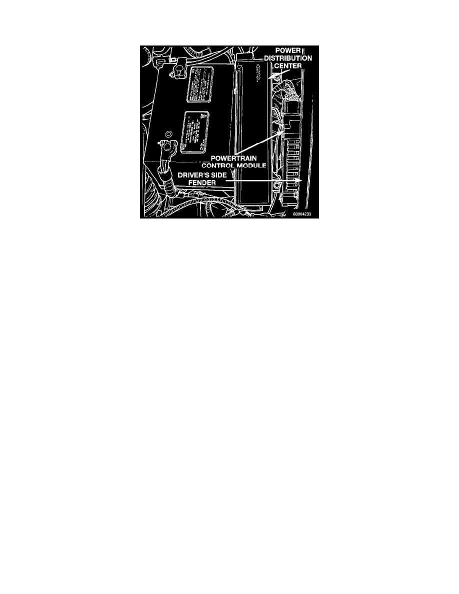
The speed control electronic control circuitry is integrated into the Powertrain Control Module (PCM). The PCM is located in the engine
compartment. The PCM speed control functions are monitored by the On-Board Diagnostics (OBD). All OBD-sensed systems are monitored by
the PCM. Each monitored circuit is assigned a Diagnostic Trouble Code (DTC). The PCM will store a DTC in electronic memory for any failure
it detects. The PCM cannot be repaired and must be replaced if faulty.
USE THE DRB SCAN TOOL TO REPROGRAM THE NEW PCM WITH THE VEHICLES ORIGINAL IDENTIFICATION NUMBER
(OIN) AND THE VEHICLES ORIGINAL MILEAGE. IF THIS STEP IS NOT DONE A DIAGNOSTIC TROUBLE CODE (DTC) MAY
BE SET.