
Voyager AWD V6-201 3.3L (1992)
Driver/Vehicle Information Display: Connector Views
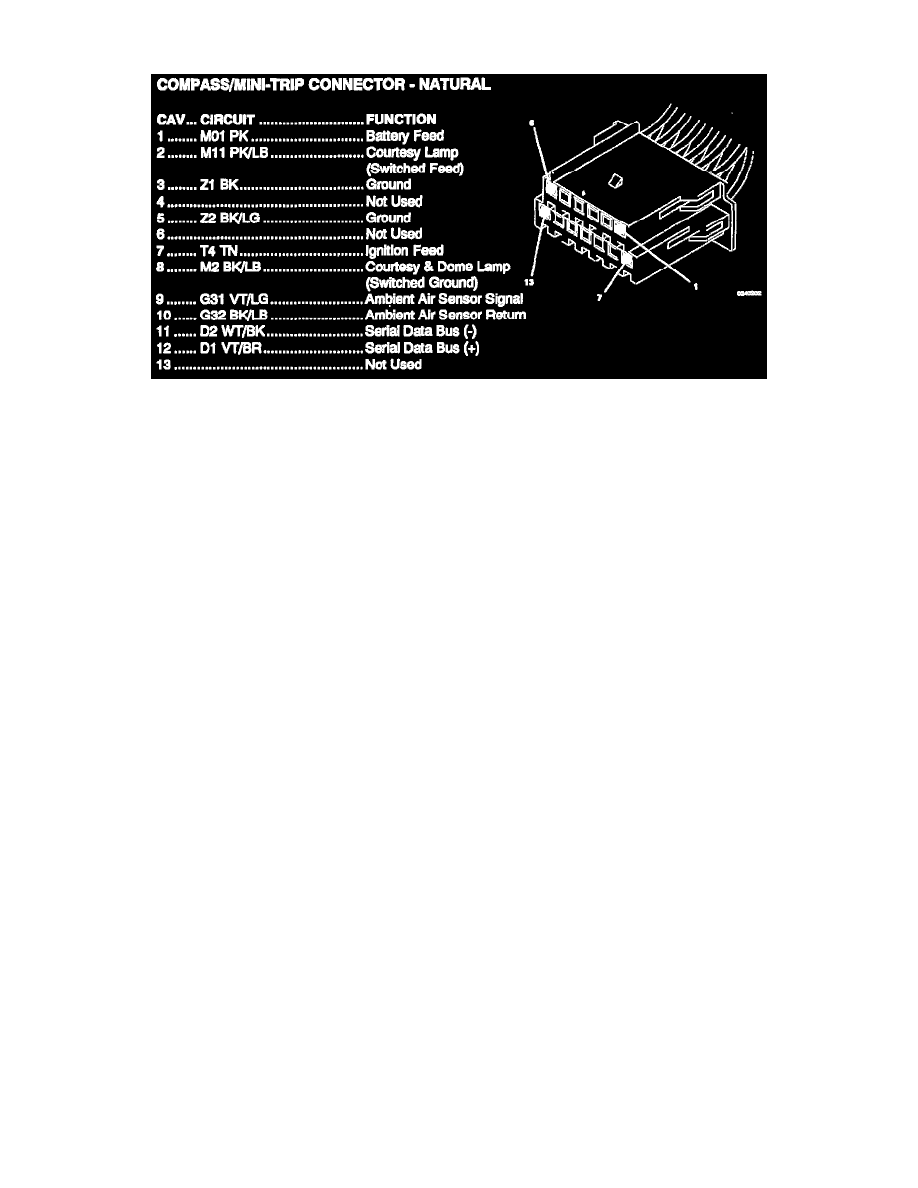
CAV CIRCUIT
FUNCTION
1
M01 PK
Battery Feed
2
M11 PK/LB
Courtesy Lamp (Switched Feed)
3
Z1 BK
Ground
4
Not Used
5
Z2 BK/LG
Ground
6
Not Used
7
T4 TN Ignition
Feed
8
M2 BK/LB
Courtesy & Dome Lamp (Switched Ground)
9
G31 VT/LG
Ambient Air Sensor Signal
10
G32 BK/LB
Ambient Air Sensor Return
11
D2 WT/BK
Serial Data Bus (-)
12
D1 VT/BR
Serial Data Bus (+)
13
Not Used