
6000 V6-173 2.8L VIN W FI (1986)
Technical Service Bulletin # 8694
Date: 860301
Steering Wheel Radio Controls - Corrected Diagnosis
Number
86-9-4
Date
3/86
Subject:
STEERING WHEEL RADIO CONTROLS - DIAGNOSIS
1986 6000 STE
When diagnosing the 1986 6000 STE Steering Wheel Radio Controls, use ONLY the information provided in the attached sheets. These sheets are a
copy of the Service Manual Section 9H, "Steering Wheel Radio
Controls".
It is imperative that only the Section 9H material be
used, as the diagnostics published in Section 8A-150-2 through 8A-150-5 are erroneous and incomplete. Use of the Section 8A diagnostics may result in
misdiagnosis and/or damage to the system. The wiring diagrams shown on pages 8A-150-0/8A-150-1 may be used as published.
STEERING WHEEL RADIO CONTROLS
NOTICE:
The steering wheel Remote Control Head is susceptible to electrical damage from electrostatic discharge, or ESD. When performing any
type of service on the Remote Control Head/Radio system you MUST discharge yourself of static electricity by touching a good vehicle
ground, such as the door post or shift lever. Failure to do so may result in damage to the Control
Head/Radio, requiring repair at an AC-Delco Repair Station. If for any reason you leave the vehicle while servicing the system, after re-entering to
continue work you must ground yourself and drain any static electrical charge. If performing Control Head/Radio checks on a new vehicle, remove the
plastic seat covers, as they increase the possibility of creating a static charge.
General Description
CONTROL OPERATION
For operation of steering wheel radio controls, see Section 9A.
CIRCUIT OPERATION
The remote radio system consists of a multifunction Remote Control Head and data transmitter located in the steering wheel, a slipring and rotating
optical data link in the steering column, and an ARC (Advanced Radio Concept) radio equipped with a serial data port for remote control.
Power for the Control Head electronics is taken from the radio fuse, and is supplied to the Control Head through a slipring. The ground and button
illumination power are also supplied to the Control Head through the sliprings (see Section 8A for wiring diagrams).
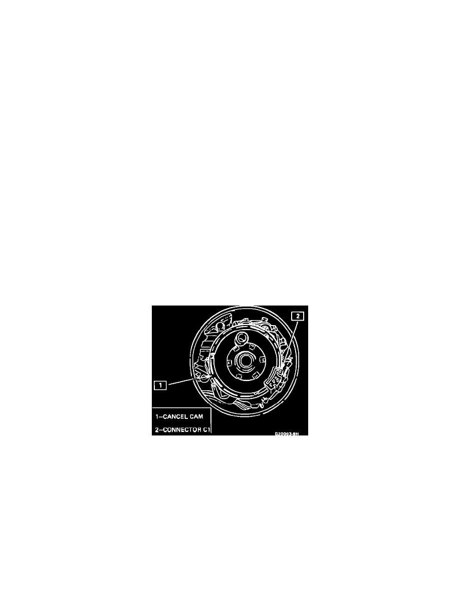
Fig. 1 Cancel Cam