
6000 V6-173 2.8L VIN W FI (1986)
8.
With IGN switch in a. Radio responds to a. If button is inoperative
RUN or ACCY and radio
all controls. All
and does not have a
on, operate all control
buttons have a similar
similar "feel" to all the
head controls.
"feel".
others, repair/replace
control head.
b.
If all buttons "feel" good and some buttons do operate, perform "Remote Control System Test".
c.
If no buttons operate and illumination is also out, perform "Control Head Power Supply Test".
d.
If no buttons operate and illumination is on, perform "Control Head Power Supply Test", "Remote Control System Test" then
"Optical/Slipring Test 1" until the problem is found.
2.
Speaker Test
If one or more speakers does not operate, test by substituting a known-good speaker designed for an ARC radio. If the substitute speaker works, replace
the speaker. If the substitute speaker does not work, check the wiring to that speaker by connecting the substitute speaker directly to the radio.
3.
Antenna Test
Check connectors at radio and antenna ends of coaxial antenna cable. Connect a known-good test antenna to the radio. The test antenna must be designed
for use with ARC radios, as ARC radios use a different size of antenna connection than conventional radios. Replace the antenna and/or coaxial cable if
the test antenna works.
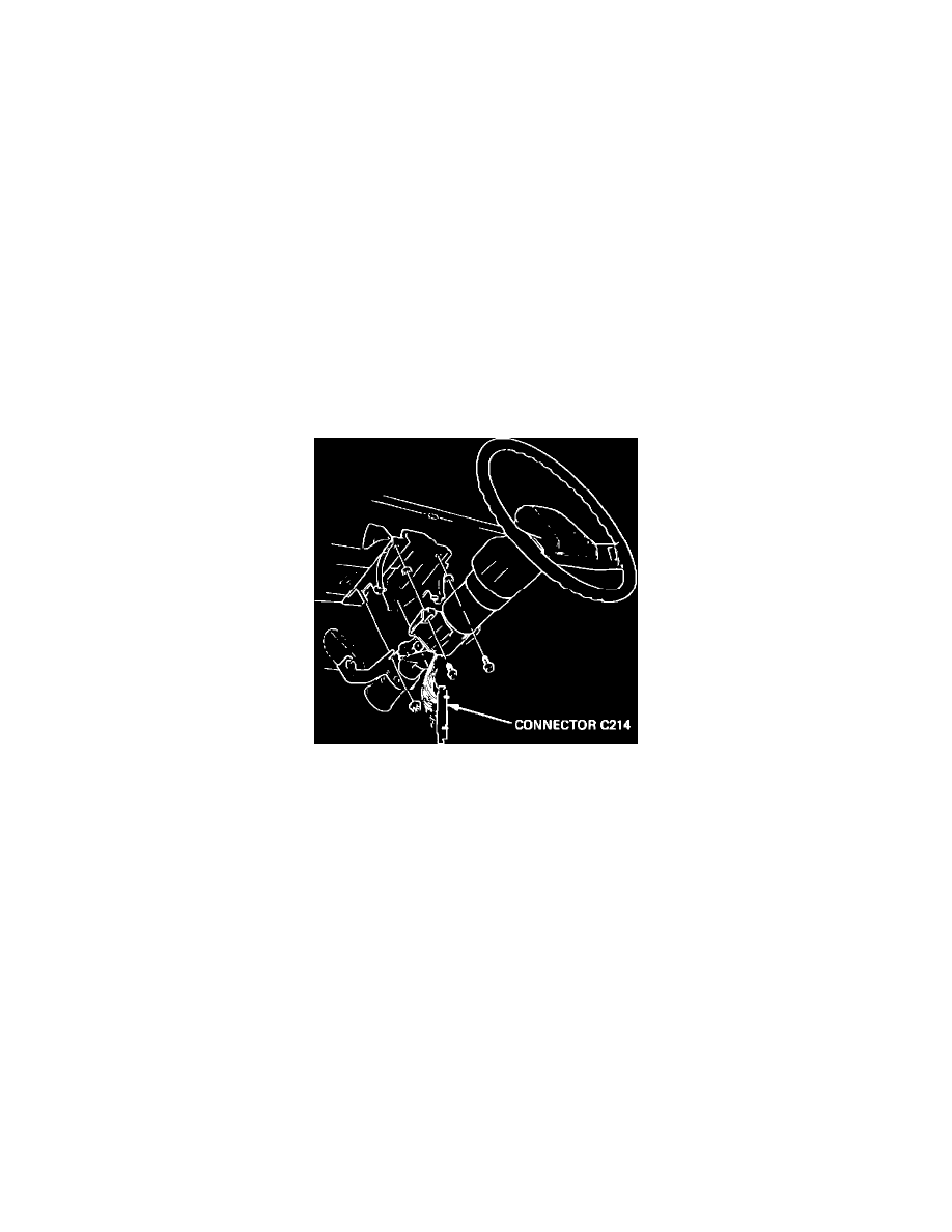
FIGURE 5 - CONNECTOR C214 (ON-CAR)
CONTROL HEAD POWER SUPPLY TEST
To expose the connector used in this test, remove the steering column filler panel (see Figure 103; Section 8C). See Figure 5 for the on-car connector
location.
Connector Chart
Figures 5 and 6 This chart is used in the same way as the "Sound System Check Chart". With connector C214 still connected, backprobe the terminals on
C214 given in Column 1, and check for the proper result given in Column 2. If you do not get the expected result given in Column 2, see Column 3 for
the appropriate action to take. All tests in this chart are to be performed with connector C214 still connected and with the IGN switch in the RUN or
ACCY position.
Connector Chart
TERMINALS (1)
EXPECTED VOLTAGE (2)
DIAG. ACTION (3)
1.
D (YEL) to ground. 1. Battery voltage. 1. Check YEL (43) wire.
2.
D (YEL) to B (LT. 2. Battery voltage. 2. Check LT. BLU/BLK BLU/BLK). (151) wire.
3.
C (GRA) to B (LT. 3. Battery voltage when 3. Check GRA (8) wire.
BLU/BLK).
headlights are on and
I/P lamps are not dimmed.
If all measurements at connector C214 are good, perform "Optical/Slipring Test 1".