
Aztek V6-3.4L VIN E (2001)
4. A State of Health DTC with a history status may be present along with a U1000 or U1255 code having a current status. This indicates that the
malfunction occurred when the ignition was ON.
5. Data link connector terminals 2 and 5 provide the connection to the class 2 serial data circuit and the signal ground circuit respectively.
7. A poor connection at terminal A would cause this condition but will not set a DTC.
8. An open in the class 2 serial data circuit between the DLC and star connector will prevent the scan tool from communicating with any module.
This condition will not set a DTC.
9. The class 2 serial data circuit is shorted to voltage or ground. The condition may be due to the wiring or due to a malfunction in one of the
modules. When testing the wire for a short, make sure there is not a module connected to the wire being tested. This test isolates the BCM class 2
serial data circuit.
11. The BCM detects that the ignition is ON and sends the appropriate power mode message to the other modules. Therefore, the BCM must remain
connected to the DLC for any other module to communicate with the scan tool. This test isolates the PCM class 2 serial data circuit.
13. This test isolates the radio class 2 serial data circuit.
15. This test isolates the EBCM class 2 serial data circuit.
17. This test isolates the SDM class 2 serial data circuit.
19. This test isolates the IPC class 2 serial data circuit.
21. This test isolates the PASS-Key(R) III class 2 serial data circuit.
23. This test isolates the auxiliary power drop Connector class 2 serial data circuit.
25. This test isolates the HUD class 2 serial data circuit.
29. If there are no current DTCs that begin with a "U", the communication malfunction has been repaired.
30. The communication malfunction may have prevented diagnosis of the customer complaint.
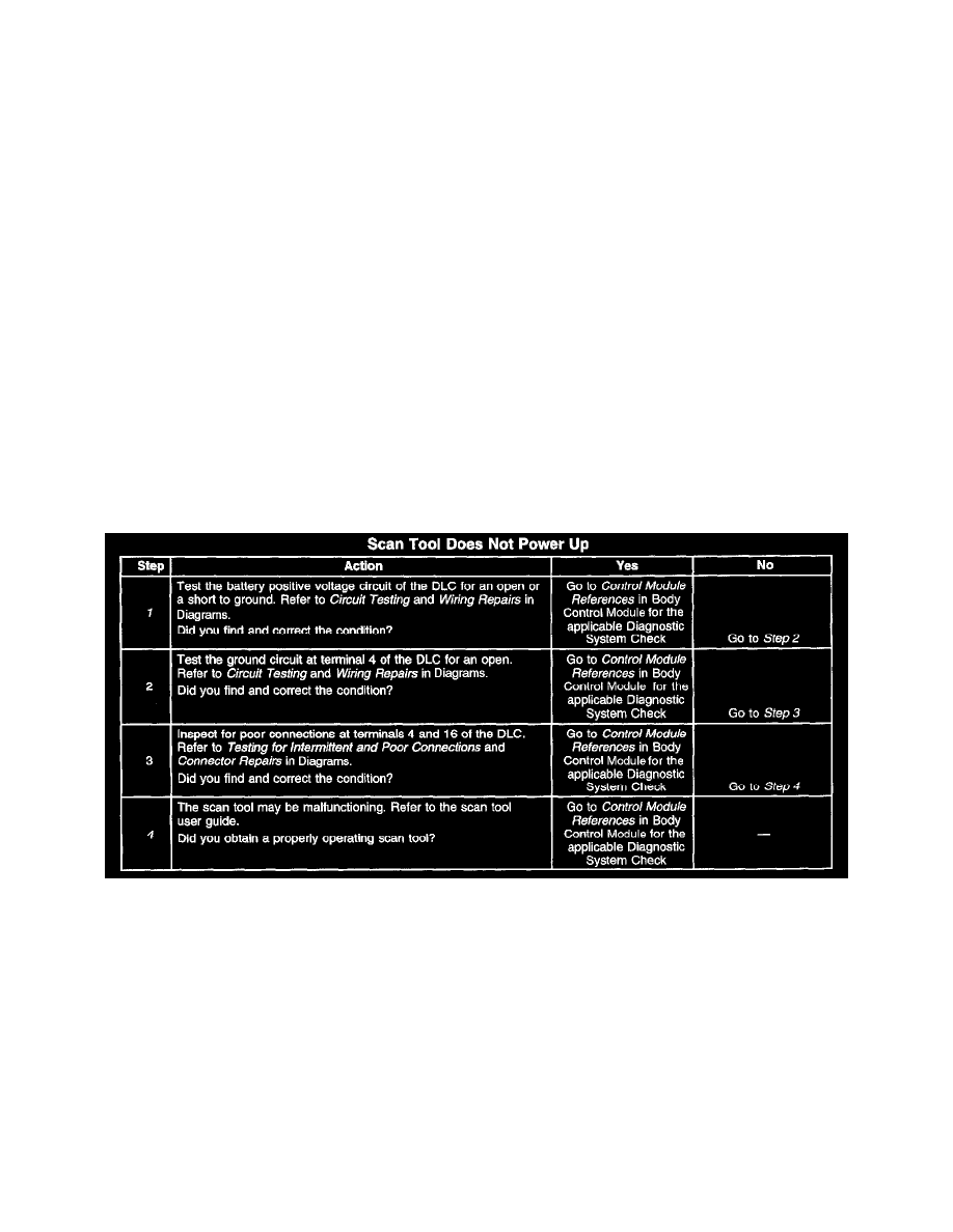
Scan Tool Does Not Power Up
CIRCUIT DESCRIPTION
The Data Link Connector (DLC) provides battery positive voltage at terminal 16 and ground at terminal 4. The DLC provides the class 2 serial data
signal at terminal 2 and signal ground at terminal 5. The scan tool will power up with the ignition OFF. Many modules, however, will not
communicate unless the Body Control Module (BCM) detects that the ignition is on and sends the appropriate power mode message.
TEST DESCRIPTION
Steps 1-4
The numbers below refer to the step numbers on the diagnostic table and the test being performed.
1. The FRT AUX fuse supplies power to terminal 16 of the DLC.
4. The battery positive voltage and ground circuits of the DLC are functioning properly. The malfunction must be due to the scan tool.