
Aztek V6-3.4L VIN E (2001)
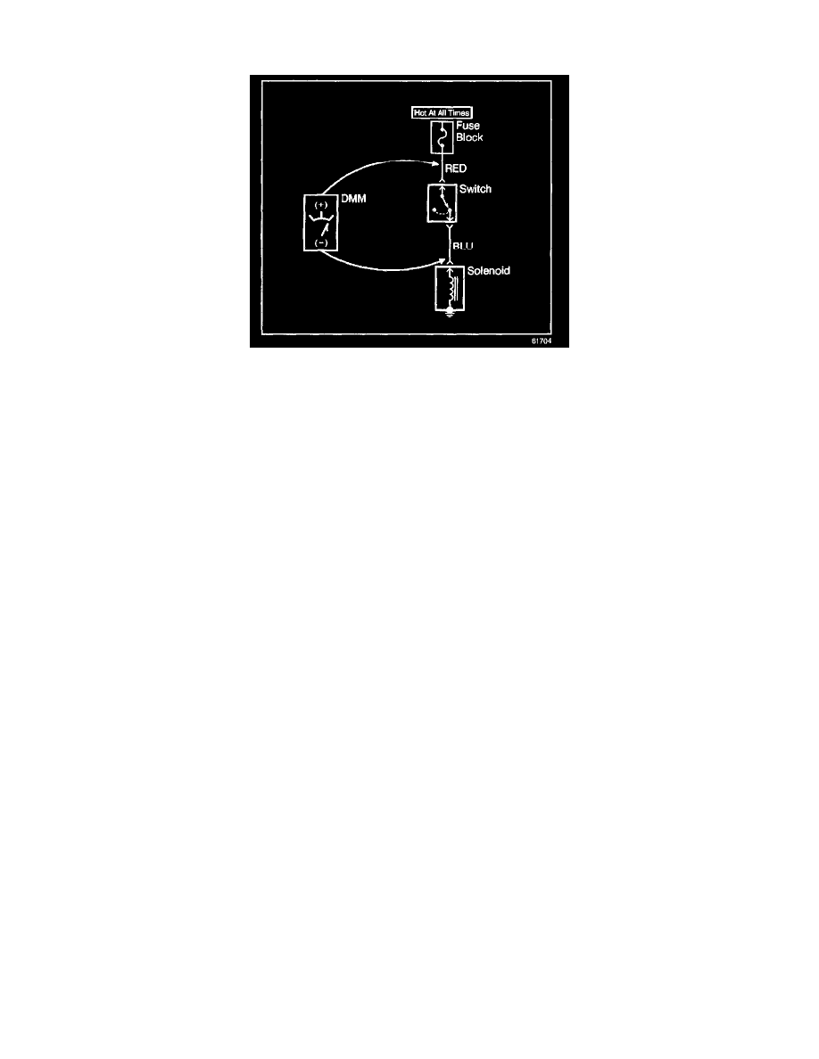
The following procedure determines the difference in voltage potential between 2 points.
1. Set the rotary dial of the DMM to the V (DC) position.
2. Connect the positive lead of the DMM to 1 point of the circuit to be tested.
3. Connect the negative lead of the DMM to the other point of the circuit.
4. Operate the circuit.
5. The DMM displays the difference in voltage between the 2 points.
Probing Electrical Connectors
IMPORTANT: Always be sure to reinstall the Connector Position Assurance (CPA) and terminal position assurance (TPA) when reconnecting
connectors or replacing terminals.
Frontprobe
Disconnect the connector and probe the terminals from the mating side (front) of the connector.
NOTE: Do not insert test equipment probes into any connector or fuse block terminal. The diameter of the test probes will deform most terminals. A
deformed terminal can cause a poor connection, which can result in system failures. Always use the J 35616-A Connector Test Adapter Kit or the J
42675 Flat Wire Probe Adapter kit in order to frontprobe terminals. Do not use paper clips or other substitutes as they can damage terminals and cause
incorrect measurements.
Backprobe
IMPORTANT:
^
Backprobe connector terminals only when specifically required in diagnostic procedures.
^
Do not backprobe a sealed (Weather Pack(R)) connector, less than a 280 series Metri-Pack connector, a Micro-Pack connector, or a flat wire
(dock and lock) connector.
^
Backprobing can be a source of damage to connector terminals. Use care in order to avoid deforming the terminal, either by forcing the test probe
too far into the cavity or by using too large of a test probe.
^
After backprobing any connector, inspect for terminal damage. If terminal damage is suspected, test for proper terminal contact.
Do not disconnect the connector and probe the terminals from the harness side (back) of the connector.
Scan Tool Snapshot Procedure
Snapshot is a recording of what a control module on the vehicle was receiving for information while the snapshot is being made. A snapshot may be used
to analyze the data during the time a vehicle condition is current. This allows you to concentrate on making the condition occur, rather than trying to
view all the data in anticipation of the fault. The snapshot contains information around a trigger point that you have determined. Only a single data list
may be recorded in each snapshot. The Scan Tool has the ability to store 2 snapshots. The ability to record 2 snapshots allows comparing hot versus cold
and good versus bad vehicle scenarios. The snapshots are stored on a 'first in, first out' basis. If a third snapshot is taken, the first snapshot stored in the
memory will be lost.
Snapshots can be 1 of 2 types:
^
Snapshot taken from the Snapshot menu choice
^
Quick Snapshot - taken from the Data Display soft key choice (Does not contain DTC information)
When a snapshot is taken, it is recorded on the memory card and may contain as many as 1200 frames of information. Because the snapshot is recorded