
Bonneville V6-231 3.8L VIN 3 SFI (1988)
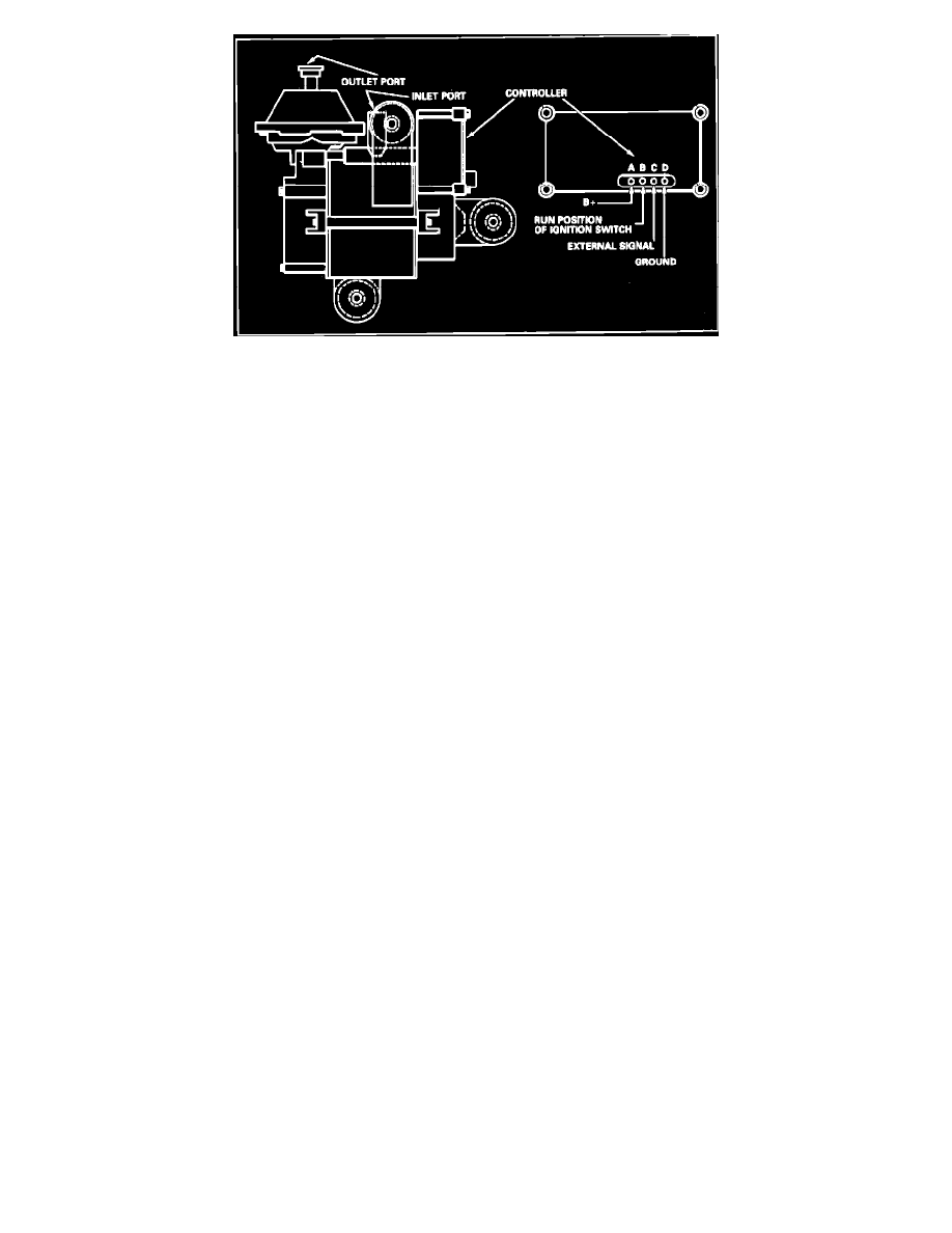
Fig. 3 Vacuum pump electrical connections
The vacuum pump outlet hose is connected to the intake manifold and the inlet hose is connected to the brake booster check valve, Fig. 2. A charcoal
filter is installed in the outlet hose to prevent harmful vapors from damaging the internal pump components.
A fusible link supplies current to the controller timer/relay at all times, while the ignition switch supplies current through a five amp fuse to the
internal on-off vacuum switch. Under low vacuum conditions (12.5 inches Hg or lower) the internal vacuum switch closes, feeding current to the
timer/relay which activates the vacuum pump motor to maintain 13.0 inches Hg of vacuum in the brake booster system. When normal vacuum conditions
are reached the internal vacuum switch opens, and the timer/relay continues to supply current to the pump for an additional five to ten seconds. The
timer/relay contacts then open stopping current to the vacuum pump motor, Fig. 3.
The system has an integral low vacuum warning system made up of a vacuum warning light switch located in the inlet hose and a warning light. When
system vacuum drops below a predetermined level, the vacuum warning light switch will sense low vacuum and activate the dash mounted warning light,
which will glow alerting the driver of low brake vacuum conditions.